Time stamp’ feature, Programmable outputs, Time stamp’ feature programmable outputs – Sumix SMX-M7xx User Manual
Page 51
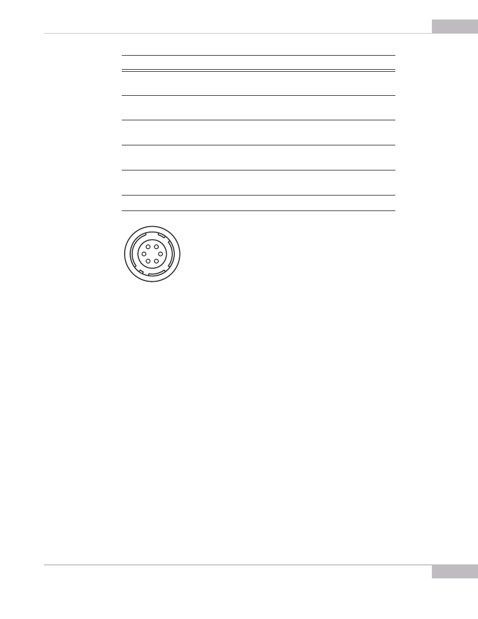
Snapshots: External Trigger Connector Pinout
51
SMX-M7xx Series USB2.0 Camera User Guide
Figure 6-4 Camera Connector View, as mounted on the camera
‘Time Stamp’ Feature
●
bit7 bit6 bit5 - three highest bits of line counter
●
bit7 - pin1 of the external connector.
●
bit6 - inverted pin4 of the external connector.
●
bit5 - Software controlled. Connected to bit 7 of register#3.
Bit6 of the Register #3 controls the mode of the 'Time stamp' feature.
0 is the Continuous mode. Each signal is connected directly to the corresponding
highest bit of line counter.
1 is Reset mode. Highest bits of the line counter are reset in the beginning of a new line.
In other words:
●
if R3.6=0, each signal is connected to the corresponding bit in the line counter
●
if R3.6=1, each signal is latched in RS trigger, which is reset in the beginning of each
line.
Programmable Outputs
Each programmable output pin can be programmed to the following output signals:
Pin Number
Direction
Signal
Polarity
1
Input
Trigger / 'Time
stamp' input
Positive
2
Output
Programmable
output
-
3
Output
Programmable
output
-
4
Input
Trigger / 'Time
stamp' input
Negative
5
Output
Programmable
output
-
6
-
Common (Ground)
-
1
2
3
4
5
6