Network requirements, Configuration considerations, Configuration procedure – H3C Technologies H3C S10500 Series Switches User Manual
Page 55
# After IRF 2 starts up, it re-joins IRF 1. You can use the display irf topology command to view the
topology information of the IRF fabric.
<Sysname> display irf topology
Topology Info
-------------------------------------------------------------------------
IRF-Port1 IRF-Port2
Switch Link neighbor Link neighbor Belong To
1 UP 3 UP 2 00e0-fc0f-8c0f
2 UP 1 UP 4 00e0-fc0f-8c0f
3 UP 4 UP 1 00e0-fc0f-8c0f
4 UP 2 UP 3 00e0-fc0f-8c0f
Switching the operating mode of IRF member switches from IRF
to standalone
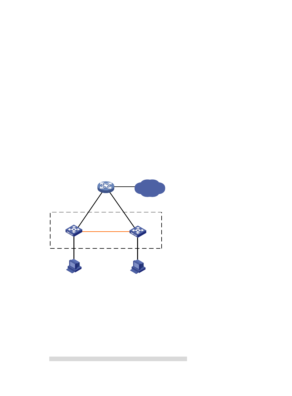
Network requirements
As shown in
, Device A and Device B are member switches of an IRF fabric.
Switch the operating mode of Device A and Device B from IRF to standalone.
Figure 17 Network diagram
XGE1/3/0/1
(IRF-port1/2)
XGE2/3/0/1
(IRF-port2/1)
GE1/4/0/2
GE2/4/0/2
Device A
Device B
GE4/0/1
GE4/0/2
IRF
IP network
Device C
Configuration considerations
•
Disconnect IRF connections. Unplug cables for the IRF connections or shut down all physical IRF
ports on the master at the CLI. This example uses the latter method.
•
After the IRF fabric is partitioned, switch the operating mode of the two member switches from IRF
to standalone.
Configuration procedure
1.
Identify the master.
<IRF> display irf
Switch Slot Role Priority CPU-Mac Description
*+1 0 Master 1 00e0-fc0a-15e0 DeviceA
49