Operating mode – H3C Technologies H3C S10500 Series Switches User Manual
Page 9
Device A and Device B in
form an IRF fabric, which has four MPUs (one active and three standby)
and two interface cards. The IRF fabric manages both the physical and software resources of Device A
and Device B.
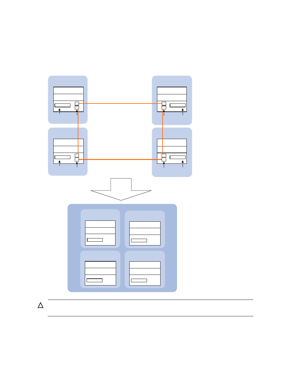
An IRF fabric with four member switches is larger in scale: it has eight MPUs (one active and seven
standby) and four interface cards, as shown in
.
Figure 3 IRF implementation schematic diagram (with four member switches)
IRF link
After an IRF
is formed.
Suppose
Device A is
the master
Master
(MemberID=1)
Slave
(MemberID=3)
Physical IRF
port
Physical IRF
port
IRF-Port2
IRF-Port1
Service
interface
Service
interface
IRF
Active MPU of the IRF
Standby MPU of the IRF
Active MPU of the
member
Device A
(MemberID=1)
Device B
(MemberID=2)
IRF-Port2
IRF-Port2
Service
interface
Service
interface
Standby MPU of the
member
Active MPU of the
member
Standby MPU of the
member
IRF-Port1
Physical IRF
port
Physical IRF
port
Active MPU of the
member
Standby MPU of the
member
Device C
(MemberID=3)
Device D
(MemberID=4)
Active MPU of the
member
Standby MPU of the
member
IRF-Port1
IRF-Port2
IRF-Port1
Slave
(MemberID=2)
Standby MPU of the IRF
Standby MPU of the IRF
Slave
(MemberID=4)
Standby MPU of the IRF
Standby MPU of the IRF
Standby MPU of the IRF
Standby MPU of the IRF
CAUTION:
In an IRF fabric, each slave switch must have at least one MPU to work normally.
This section uses
to explain the concepts that you might encounter when working with IRF.
Operating mode
A switch can operate in one of the following two modes:
3