Network requirements – H3C Technologies H3C S7500E Series Switches User Manual
Page 94
3-30
Total associations : 1
Configuring MPLS VPN Time Synchronization in Client/server Mode
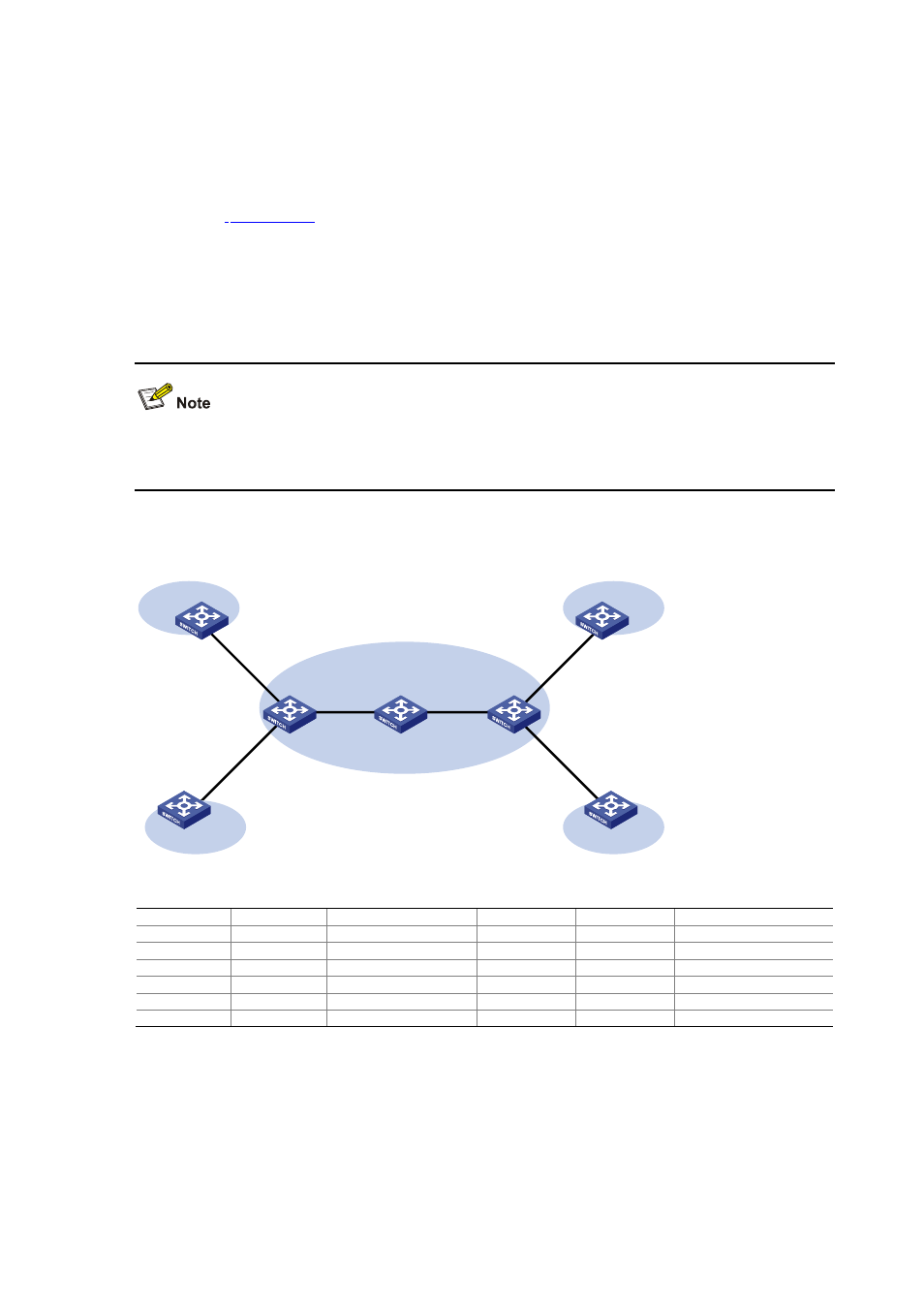
Network requirements
As shown in
, two VPNs are present on PE 1 and PE 2: VPN 1 and VPN 2. CE 1 and
CE 3 are devices in VPN 1. To synchronize the time between CE 1 and CE 3 in VPN 1, perform
the following configurations:
z
CE 1’s local clock is to be used as a reference source, with the stratum level of 1.
z
CE 3 is synchronized to CE 1 in the client/server mode.
At present, MPLS VPN time synchronization can be implemented only in the unicast mode
(client/server mode or symmetric peers mode), but not in the multicast or broadcast mode.
Figure 3-13 Network diagram for MPLS VPN time synchronization configuration
CE 1
CE 2
CE 4
CE 3
PE 1
PE 2
P
VPN 1
VPN 2
VPN 1
VPN 2
Vlan-int 10
Vlan-int 10
MPLS backbone
Vlan-int 20
Vlan-int 20
Vlan-int 30
Vlan-int 30
Vlan-int 40
Vlan-int 40
Vlan-int 50
Vlan-int 50
Vlan-int 60
Vlan-int 60
Device Interface
IP address
Device
Interface IP
address
CE 1
Vlan-int 10
10.1.1.1/24
PE 1
Vlan-int 10
10.1.1.2/24
CE 2
Vlan-int 20
10.2.1.1/24
Vlan-int 30
172.1.1.1/24
CE 3
Vlan-int 50
10.3.1.1/24
Vlan-int 20
10.2.1.2/24
CE 4
Vlan-int 60
10.4.1.1/24
PE 2
Vlan-int 50
10.3.1.2/24
P
Vlan-int 30
172.1.1.2/24
Vlan-int 40
172.2.1.2/24
Vlan-int 40
172.2.1.1/24
Vlan-int 60
10.4.1.2/24