Configuration procedure – H3C Technologies H3C WX5500E Series Access Controllers User Manual
Page 37
29
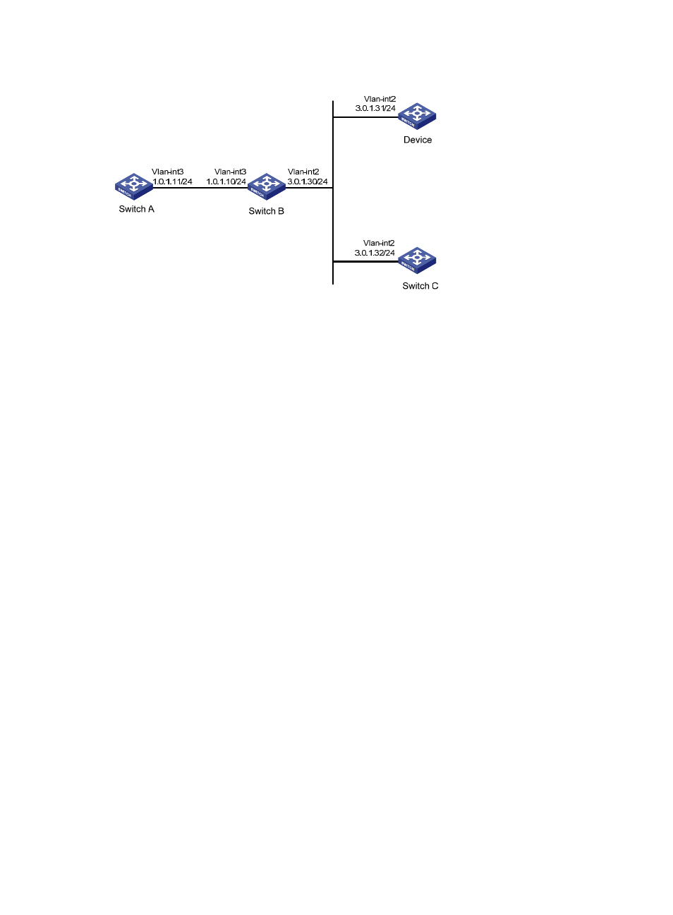
Figure 14 Network diagram
Configuration procedure
1.
Set the IP address for each interface as shown in
. (Details not shown.)
2.
Configure the device:
# Configure the device to operate in multicast server mode and send multicast messages through
VLAN-interface 2.
[Device] interface vlan-interface 2
[Device-Vlan-interface2] ntp-service multicast-server
3.
Configure Switch C:
# Configure Switch C to operate in multicast client mode and receive multicast messages on
VLAN-interface 2.
<SwitchC> system-view
[SwitchC] interface vlan-interface 2
[SwitchC-Vlan-interface2] ntp-service multicast-client
Because Switch C and the device are on the same subnet, Switch C can receive the multicast
messages from the device without being enabled with the multicast functions and can synchronize
to the device.
# Display the NTP status of Switch C after clock synchronization.
[SwitchC-Vlan-interface2] display ntp-service status
Clock status: synchronized
Clock stratum: 3
Reference clock ID: 3.0.1.31
Nominal frequency: 64.0000 Hz
Actual frequency: 64.0000 Hz
Clock precision: 2^7
Clock offset: 0.0000 ms
Root delay: 31.00 ms
Root dispersion: 8.31 ms
Peer dispersion: 34.30 ms
Reference time: 16:01:51.713 UTC Sep 19 2012 (C6D95F6F.B6872B02)
The output shows that Switch C has synchronized to the device. The stratum level of Switch C is 3,
and that of the device is 2.