Internal connections – Grass Valley Trinix Multiviewer Installation User Manual
Page 51
51
TRINIX — TMV Installation and Service Manual
Section 2 — Hardware Installation
The TMV boards must be entered in the Hardware table in output order
from least to greatest. Cascading will not function correctly if this instruc-
tion is not followed.
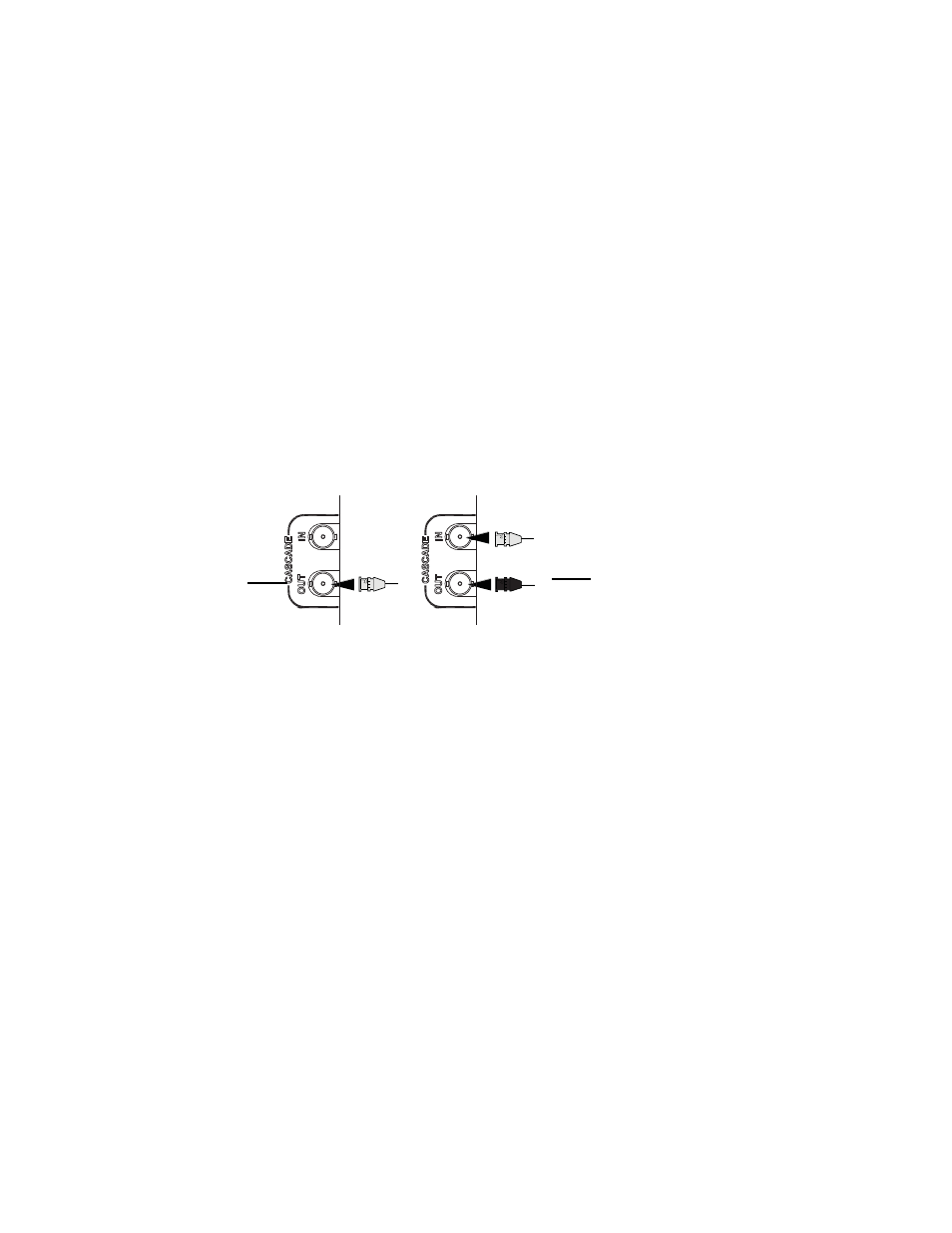
Follow these steps to connect or cascade multiple TMV boards:
1.
Connect the first cable from the CASCADE OUT on the first board to
the CASCADE IN connection on the second board. This is shown by the
gray connection in
.
2.
Connect the next cable from the CASCADE OUT on the second board
to the CASCADE IN connection on the next board if needed. This is
shown by the Black connection in
Note
The colors mentioned in the above text and in
are for demonstration
purposes only.
Figure 9. CASCADE Connections
Internal Connections
The TMV board is installed in a Trinix routing switcher. This connection
provides access to 32 Video Inputs along with the associated embedded
audio. These connections use embedded audio. The TMV receives Linear
Time Code (LTC) internally from the Broadlinx board
Time Code Pin-Outs
The LTC connections are found on J145 “GPIO/TC” pins 5 & 6 for the
512x1024 frame (
071873500_TMV_Cascade
Connect the first (Gray)
cable from the CASCADE
OUT to the CASCADE IN
connection
Connect the second (Black)
cable from the CASCADE OUT
to the CASCADE IN connection
on the next board
1
st
Board
2
nd
Board