HEIDENHAIN iTNC 530 (340 49x-01) User Manual
Page 327
HEIDENHAIN iTNC 530
327
8.4 Cy
cles f
o
r Milling P
o
c
k
ets, St
uds and Slots
8
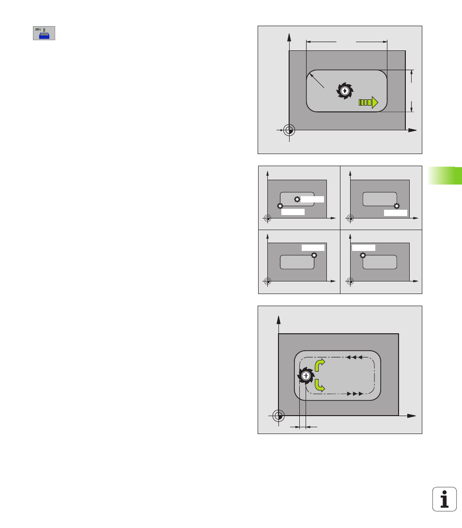
Machining operation (0/1/2)
Q215: Define the
machining operation:
0: Roughing and finishing
1: Only roughing
2: Only finishing
Side finishing and floor finishing are only executed if
the finishing allowances (Q368, Q369) have been
defined.
8
1st side length
Q218 (incremental value): Pocket
length, parallel to the reference axis of the working
plane.
8
2nd side length
Q219 (incremental value): Pocket
length, parallel to the minor axis of the working plane.
8
Corner radius
Q220: Radius of the pocket corner: If
you make no entry here, the TNC assumes that the
corner radius is equal to the tool radius.
8
Finishing allowance for side
Q368 (incremental
value): Finishing allowance in the working plane.
8
Angle of rotation
Q224 (absolute): Angle by which
the entire pocket is rotated. The center of rotation is
the position at which the tool is located when the
cycle is called.
8
Pocket position
Q367: Position of the pocket in
reference to the position of the tool when the cycle is
called (see figure at center right):
0: Tool position = Center of pocket
1: Tool position = Lower left corner
2: Tool position = Lower right corner
3: Tool position = Upper right corner
4: Tool position = Upper left corner
8
Feed rate for milling
Q207: Traversing speed of the
tool in mm/min while milling.
8
Climb or up-cut
Q351: Type of milling operation with
M03.
+1 = climb milling
–1 = up-cut milling
X
Y
Q219
Q218
Q207
Q22
0
X
Y
X
Y
X
Y
X
Y
Q367=0
Q367=1
Q367=2
Q367=3
Q367=4
X
Y
k
Q351=+1
Q351=1