HEIDENHAIN iTNC 530 (340 49x-01) User Manual
Page 353
HEIDENHAIN iTNC 530
353
8.4 Cy
cles f
o
r Milling P
o
c
k
ets, St
uds and Slots
8
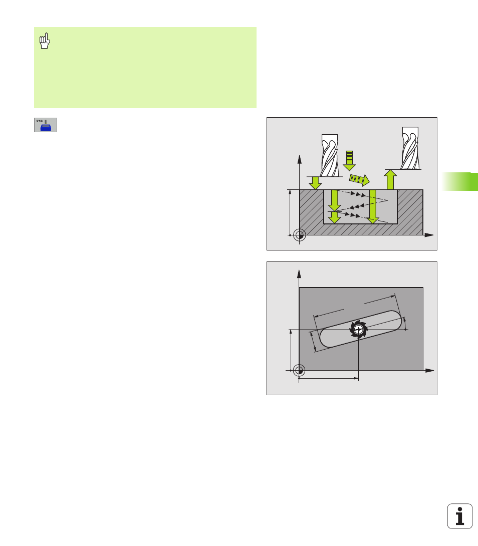
Set-up clearance
Q200 (incremental value): Distance
between tool tip and workpiece surface.
8
Depth
Q201 (incremental value): Distance between
workpiece surface and bottom of slot.
8
Feed rate for milling
Q207: Traversing speed of the
tool in mm/min while milling.
8
Plunging depth
Q202 (incremental value): Total
extent by which the tool is fed in the tool axis during
a reciprocating movement.
8
Machining operation (0/1/2)
Q215: Define the
machining operation:
0: Roughing and finishing
1: Only roughing
2: Only finishing
8
Workpiece surface coordinate
Q203 (absolute
value): Coordinate of the workpiece surface.
8
2nd set-up clearance
Q204 (incremental value): Z
coordinate at which no collision between tool and
workpiece (clamping devices) can occur.
8
Center in 1st axis
Q216 (absolute value): Center of
the slot in the reference axis of the working plane.
8
Center in 2nd axis
Q217 (absolute value): Center of
the slot in the minor axis of the working plane.
8
1st side length
Q218 (value parallel to the reference
axis of the working plane): Enter the length of the slot
8
2nd side length
Q219 (value parallel to the secondary
axis of the working plane): Enter the slot width. If you
enter a slot width that equals the tool diameter, the
TNC will carry out the roughing process only (slot
milling).
Enter in MP7441 bit 2 whether the TNC should output an
error message (bit 2=1) or not (bit 2=0) if a positive depth
is entered.
Danger of collision!
Keep in mind that the TNC reverses the calculation for pre-
positioning when a positive depth is entered. This
means that the tool moves at rapid traverse in the tool axis
at safety clearance below the workpiece surface!
X
Z
Q200
Q201
Q207
Q202
Q203
Q204
X
Y
Q219
Q218
Q217
Q216
Q224