3 additional grounding of the enclosure – SMA WB 3000-21 Installation User Manual
Page 34
6 Electrical Connection
SMA Solar Technology AG
34
WB3-5TL-21-IA-en-10
Installation Manual
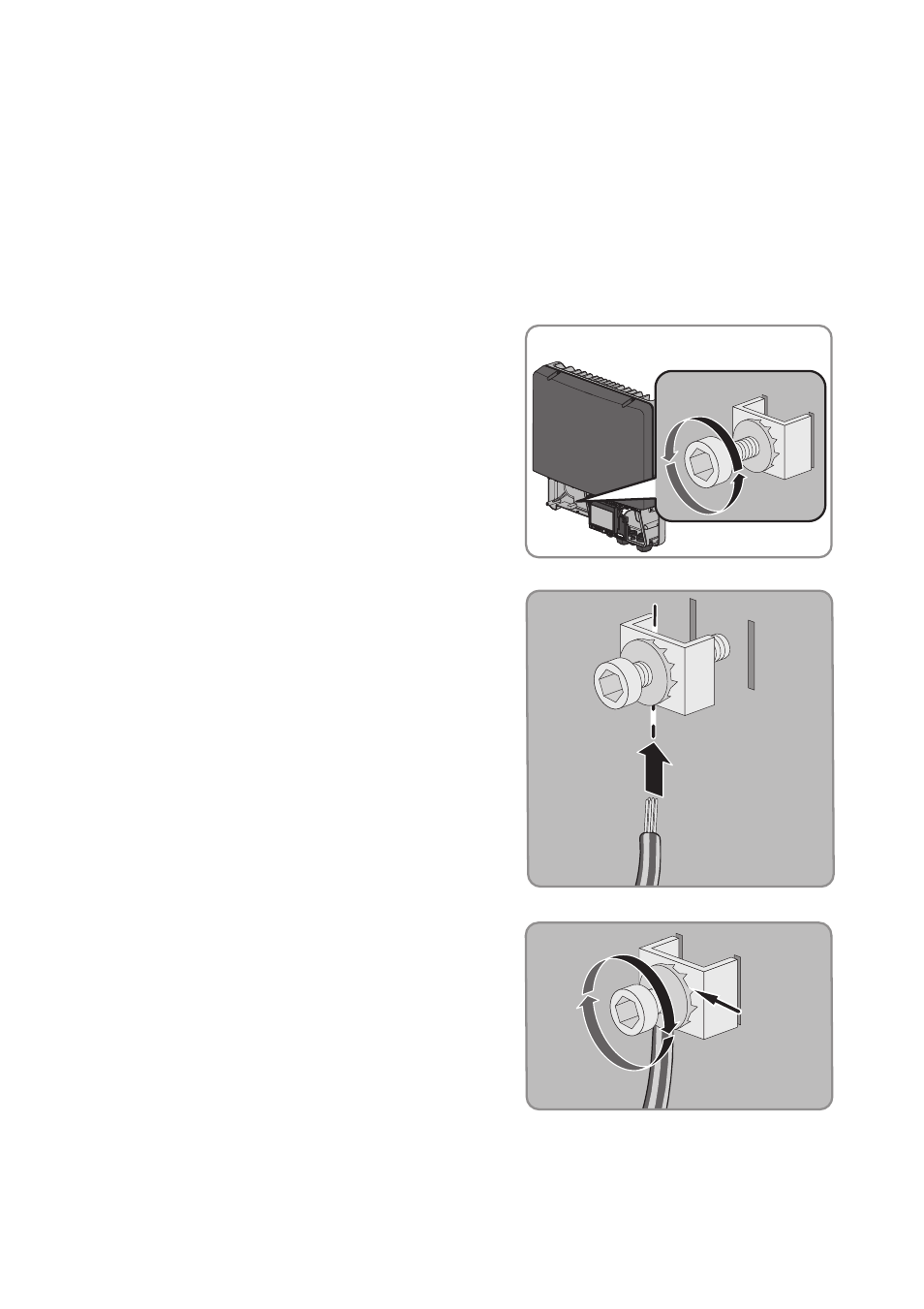
6.3.3 Additional Grounding of the Enclosure
If a second protective conductor or equipotential bonding is required locally, you can also ground
the enclosure. This prevents touch current if the original protective conductor fails.
Cable requirement:
☐ Maximum grounding cable cross-section: 10 mm²
1. Strip the grounding cable insulation.
2. Loosen the screws using an Allen key (AF 4), until
the grounding cable can be led under the clamping
bracket.
3. Feed the grounding cable under the clamping
bracket. Set the protective conductor to the left.
4. Tighten the clamping bracket with the screw and
conical spring washer (torque: 6 Nm). The teeth of
the conical spring washer must face the clamping
bracket.