Top and bottom panel features, Top and bottom panel features 4, Chapter 1 – Lanner LEC-3010 User Manual
Page 6: Introduction
4
Introduction
Chapter 1
Embedded and Industrial Computing
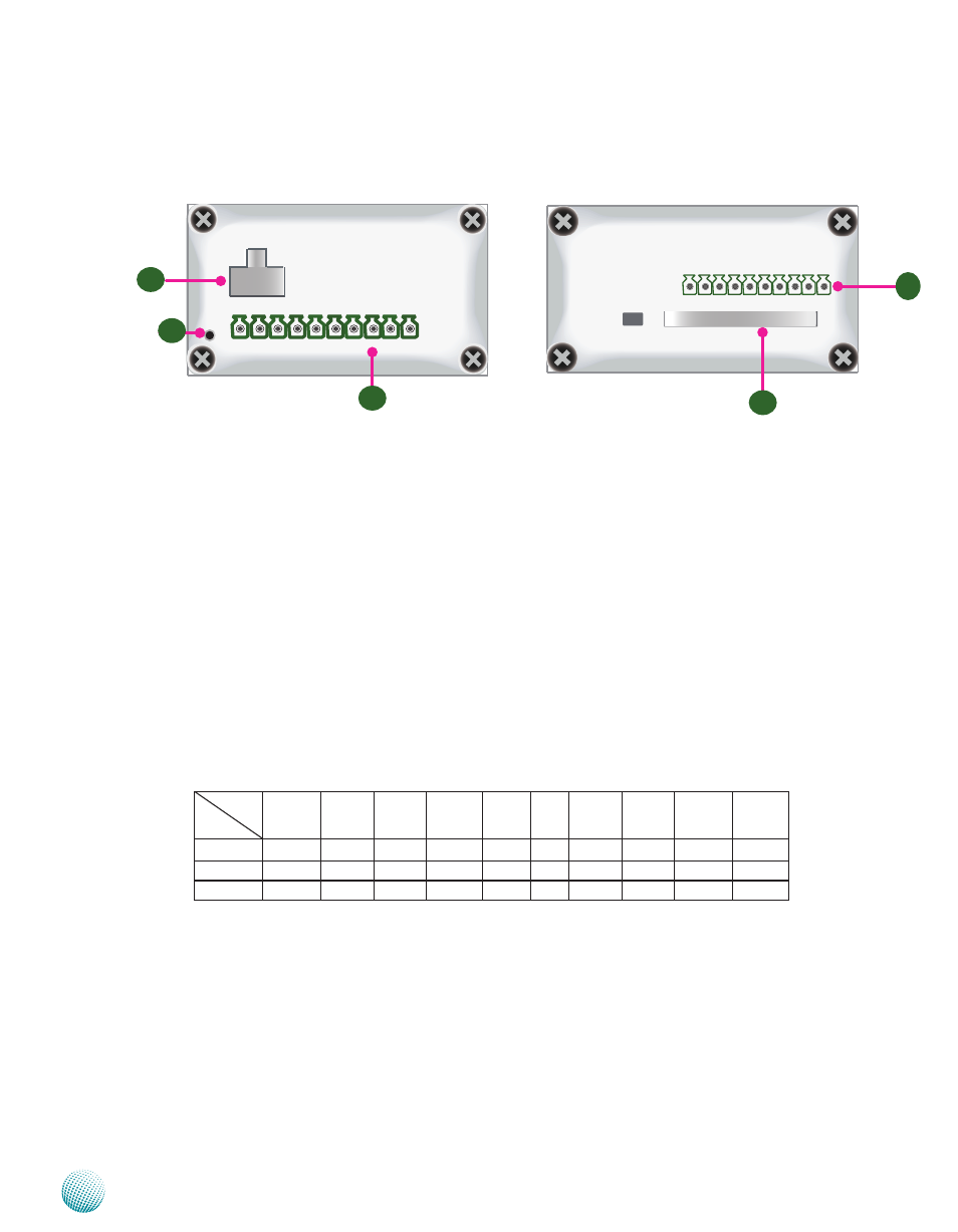
Top and Bottom Panel Features
R1 Reset Switch: A hardware reset switch
Use a pointed object to press it 5 seconds then release it to reset the system without
turning off the power
R2 Power Socket
Power supply through 1x2-pin Phoenix Contact with 12~36V dual power source
R3 Digital Input/Output port:
The digital input/output (DIO) peripheral is provided through 10-pin terminal block
connector
Pin 2 to 5: Digital Inputs
Pin 7 to10: Digital Output
R4 CompactFlash Connector
One Type I / Type II CompactFlash card slot is provided by the system
R5 10-pin Phoenix Contact Terminal Block connector for COM5 and COM6 ports
It supports dip switch selection among RS-232, RS-422 and 485 The following table lists
the pin assignments:
COM NO.
Port Type
Pin 1
Pin 2
Pin 3
Pin 4
Pin 5
Pin 6
PIN7
PIN 8
PIN 9
Pin10
RS-232
GND
CTS5# SOUT5 SIN5 RTS5# GND CTS6# SOUT6
SIN6
RTS6#
RS-422
GND
RX-
RX+
TX+
TX- GND
RX-
RX+
TX+
TX-
RS-485
GND
NC
NC
DATA+ DATA- GND
NC
NC
DATA+ DATA-
R2
R4
1 2 3 4 5 6 7 8 9 1 0
-
+
R1
R5
R3