Magnum Energy Magnum Panel (MP Series) User Manual
Page 35
Page 28
© 2011 Magnum Energy, Inc.
3.0 Installation
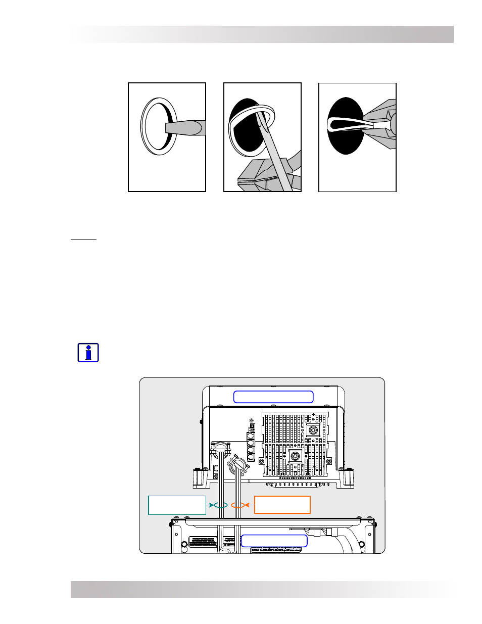
Figure 3-11, Removing Knockouts
3.3.3
Connect and Separate Inverter AC Wires
Before mounting the inverter on the MP enclosure, we highly recommend using the wires provided
in the MP AC Wiring Kit (Item 6, Figures 3-1 and 3-2) and connecting them to the inverter’s AC
wiring terminals (see Figure 4-1 for MS4024 inverters, Figure 4-2 for MS-PAE Series inverters, or
refer to the inverters owner’s manual). It is possible to connect these wires after the inverter is
mounted, but space and access is limited - especially when installing multiple inverters side-by-
side on an MP enclosure system.
When connecting the inverter’s AC input and output wires, take time to separate the wires into
two bundles (AC input and AC output), and route each bundle thru different strain-reliefs on the
inverter as shown in Figure 3-12. This will help to ensure they are connected to the correct termi-
nals in the MP enclosure after the inverter is mounted. Refer to Table 3-3 for information on each
wire in the AC wiring kit and where they are used.
Info: Once the AC wires are connected inside the inverter, ensure the AC wiring access
plate is reattached before mounting the inverter on the MP enclosure.
Figure 3-12, Connect and Separate Inverter AC Wires
Inverter AC
Output Wires
Inverter AC
Input Wires
MP Enclosure
Magnum Inverter
As shown in Figure 3-11, remove the knockouts by tapping the edge with a straight bladed
screwdriver and a hammer, then
twist out with pliers.
Ensure no debris remains inside the MP
enclosure after removing the knockouts.