0 installation, 1 sizing the grounding electrode conductors, Table 3-6, ac grounding electrode conductor sizing – Magnum Energy Magnum Panel (MP Series) User Manual
Page 63: Mp e
Page 56
© 2011 Magnum Energy, Inc.
3.0 Installation
3.11.1
Sizing the Grounding Electrode Conductors
AC Side - The size of the AC Grounding Electrode Conductor (GEC–AC) depends on the size of
the largest ungrounded conductor feeding the AC load center. One #8 AWG (8.4 mm
2
) copper
conductor will serve as an AC grounding electrode conductor for AC power conductors smaller than
and including #2 AWG (33.6 mm
2
) copper. See
Table 3-6 for additional values.
Table 3-6, AC Grounding Electrode Conductor Sizing
Size of Largest Ungrounded
Conductor
Minimum Size of Grounding
Electrode Conductor
#2 AWG or smaller
#8 AWG
(8.4 mm
2
)
#1 to #1/0 AWG
#6 AWG
(13.3 mm
2
)
#2/0 or #3/0 AWG
#4 AWG
(21.1 mm
2
)
Over #3/0 AWG
through 350 kcmil
#2 AWG
(33.6 mm
2
)
DC Side - To size the DC grounding electrode conductor, fi rst determine which one of the following
three methods will be used to connect the DC and AC grounding points in the inverter’s two
electrical systems (AC and DC) to the common “earth” ground.
Info: There are many variables to consider when choosing the size of the DC grounding
electrode conductor. The MP enclosure provides the means to ground both the AC and
DC to a single ground, and when feasible, the Single Connection to Ground (Method 1)
is recommended. With this method the NEC allows a #6 AWG wire, which makes the
overall installation simpler and less costly.
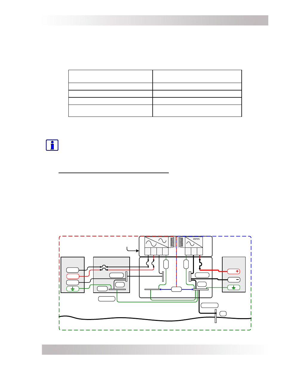
1.
Single Connection to Ground (Method 1): The AC Grounding Electrode Conductor
(GEC–AC) is bonded to the DC ground point and the DC Grounding Electrode Conductor (GEC–DC)
is the only connection to the grounding electrode, which must be a rod, pipe, or plate electrode
(see Figure 3-31).
Normally the size of the DC grounding electrode conductor must be no less than the size of the
battery bank’s negative cable. However, in this method, since there is only one connection to the
ground rod the NEC allows an exception. The DC grounding electrode conductor is not required
to be larger than #6 AWG (13 mm
2
) copper. The reasoning for allowing this smaller grounding
electrode conductor is that it is only required to stabilize the system voltage with respect to earth,
and the other properly-sized conductors in each electrical system will safely carry any fault currents
if they occur.
DC
S
OURCE
M
AIN
AC P
ANEL
.
H
O
T
1
.
N
E
U
T
.
G
N
D
.
H
O
T
2
.
D
C
S
IDE
.
A
C
S
IDE
MP E
NCLOSURE
AC
S
OURCE
DC side dedicated
DC Electrical
System
AC Electrical
System
Grounding System
.
G
N
D
.
P
O
S
.
N
E
G
GBB
SBJ
GEC-DC
GE
GBB
SBJ
M
AGNUM
I
NVERTER
GEC-AC
GC-DC
BAT
GC-AC
HOT 1
HOT 2
NEUT
BAT
EG
C
EG
C
Figure 3-31, Single Connection to DC Ground Rod (Method 1)