Fig.5, Fig.4, Preparation – Sealey SAC3153B User Manual
Page 3: Operation
3. PREPARATiON
3.1. remove compressor from packaging and inspect for any
shortages or damage. If anything is found to be missing or
damaged contact your supplier.
3.2.
save the packing material for future transportation of the
compressor. We recommend that you store the packing in a
safe location, at least for the period of the guarantee. then, if
necessary, it will be easier to send the compressor to the
service centre.
3.3.
confirm that the mains voltage corresponds with the voltage
shown on the compressor data plate.
3.4.
Assemble the wheels and swivel castor using the nuts, bolts
and washers supplied (fig.8).
3.5.
the compressor should be operated on a horizontal flat
surface, or one that does not exceed 5° either transversely
(tyres fully inflated to 1.5bar) or longitudinally with chocks
(fig.3), and should be in a position that allows good air
circulation around the unit (see 1000mm nominal).
3.6.
Before using the compressor check the oil level by referring
to the oil sight glass (fig.4c). on a horizontal surface, if the
oil level is not up to the red centre mark it should be further
topped up with recommended oil (see section 5.7). to top up
unscrew plug (fig.4B).
3.7.
screw the back half of a filter unit into the port openings in
each head as shown in (fig.4.A). Place a filter cover over
each threaded rod protruding from the back half of the filter
and secure each with a wing nut. refer also to (fig.7).
fig.4
A
c
drain plug
B
Breather (at rear)
A
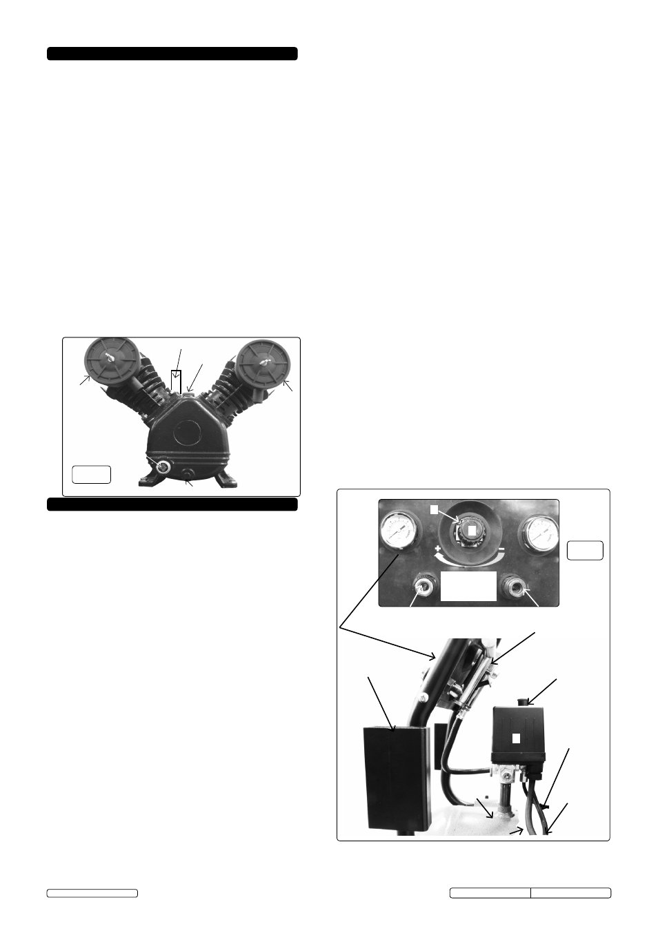
fig.5
2
1
4
5
3
6
Ac supply
restart
decompression
tube
switch/motor cable
Pull up (on)
push down (off)
receiver
manifold
regulated supply
non regulated supply
(receiver pressure)
control Panel
and
Ancilliaries
utility brackets
4.3.5. stop the compressor by pushing the switch knob (see fig.5.1)
downwards. the compressed air inside the compressor head
will flow out via the air line tube situated beneath the switch
housing. restart is made easier and prevents the motor from
being damaged.
dO NOT, other than in an emergency, stop
the compressor by switching off the mains power, or by
pulling the plug out, as the pressure relief will not then occur
and motor damage may result upon restart.
When the compressor runs correctly and is stopped correctly
there will be:
(a) A whistle of compressed air when the motor stops,
(b) A protracted whistle (about 20-25 seconds) when the
compressor starts with no pressure in the tank.
4.3.6. the output pressure is regulated by the pressure regulator
(fig.5.2). turn the knob clockwise to increase pressure and
counterclockwise to reduce it. the knob can be locked at any
required setting by tightening the locking ring (fig.5.5) up
against the underside of the knob. to determine the correct
working pressure for any piece of equipment check the
corresponding manual. When the compressor is not being
used set the regulated pressure to zero so as to avoid
damaging the pressure reducer.
note: a) If the motor does not cut in and out, but runs
continuously when using an air appliance, the capacity of the
compressor may be too small for the equipment or tool.
b) the gauge (fig.5.4) indicates the pressure inside the
main tank. the gauge (fig.5.3) indicates the
pressure supplied to the air equipment. should the pressure
in the main tank exceed the pre-set switch (fig.5.1)
maximum, the safety valve (fig.5.6) will activate.
WARNiNG! For this reason dO NOT tamper with, or
adjust, the switch or safety valve.
4.3.7. the compressor is fitted with a reset trip, located in the
connection box on top of the motor. the reset button is on the
side of the box (fig.2). should the trip activate, leave for 1
minute before pressing the button to reset. for possible
causes of trip activation and remedies see section 6
troubleshooting.
WARNiNG! Ensure that you have read, understood and
apply Section 1 safety instructions.
4.1. iMPORTANT. The use of extension leads to connect this
compressor to the mains is not recommended as the
resulting voltage drop reduces motor, and therefore
pump, performance and could damage your compressor.
4.2. Take care when selecting tools for use with the
compressor. Air tool manufacturers normally express the
volume of air required to operate a tool in cubic feet per
minute (cfm). This refers to free air delivered by the
compressor (‘air out’) which varies according to the
pressure setting. do not confuse this with the
compressor displacement which is the air taken in by
the compressor (‘air in’). ‘Air out’ is always less than ‘air
in’ - due to losses within the compressor. 4.3.
STARTiNG THE COMPRESSOR.
4.3.1. Your compressor is fitted with a push/pull type on/off
switch. to turn the compressor "on" pull the switch knob
upwards. to turn the compressor "off" push the knob
downwards. (see fig.5.1)
4.3.2. check that the on/off switch is in the “off” position and
the regulator tap (fig.5.2) is closed (Zero ‘0’ bar).
4.3.3. Plug mains lead into mains supply and start the compressor
by pulling the switch knob (fig.5.1) upwards.
4.3.4. leave the compressor running with no air line or tools
connected, and regulator (fig.5.3) set to maximum pressure
(fully clockwise). make sure that the pressure in the tank
rises and that the compressor stops automatically when the
maximum pressure is reached. this value is written on the
specification plate and shown on the gauge (fig.5.4). this
may take in excess of 5 minutes. the compressor will now
operate automatically. the pressure switch (fig.5.1) stops the
motor when the maximum tank pressure is reached and
restarts it when pressure falls below the minimum threshold
approximately 2bar (29psi) less than the maximum pressure.
4. OPERATiON
Original Language Version
sAc3153B/sAc3203B Issue no: 1 - 01/06/13
© Jack sealey limited 2013