Natural convection (vn), Forced convection (vf), Release of counterweights – MCZ Forma Wood 115 User Manual
Page 21: Positioning
INSTALLATION AND USE MANUAL
Chapter 4
page
21
Installation and assembly
Technical service – MCZ S.p.A. all rights reserved - Reproduction prohibited
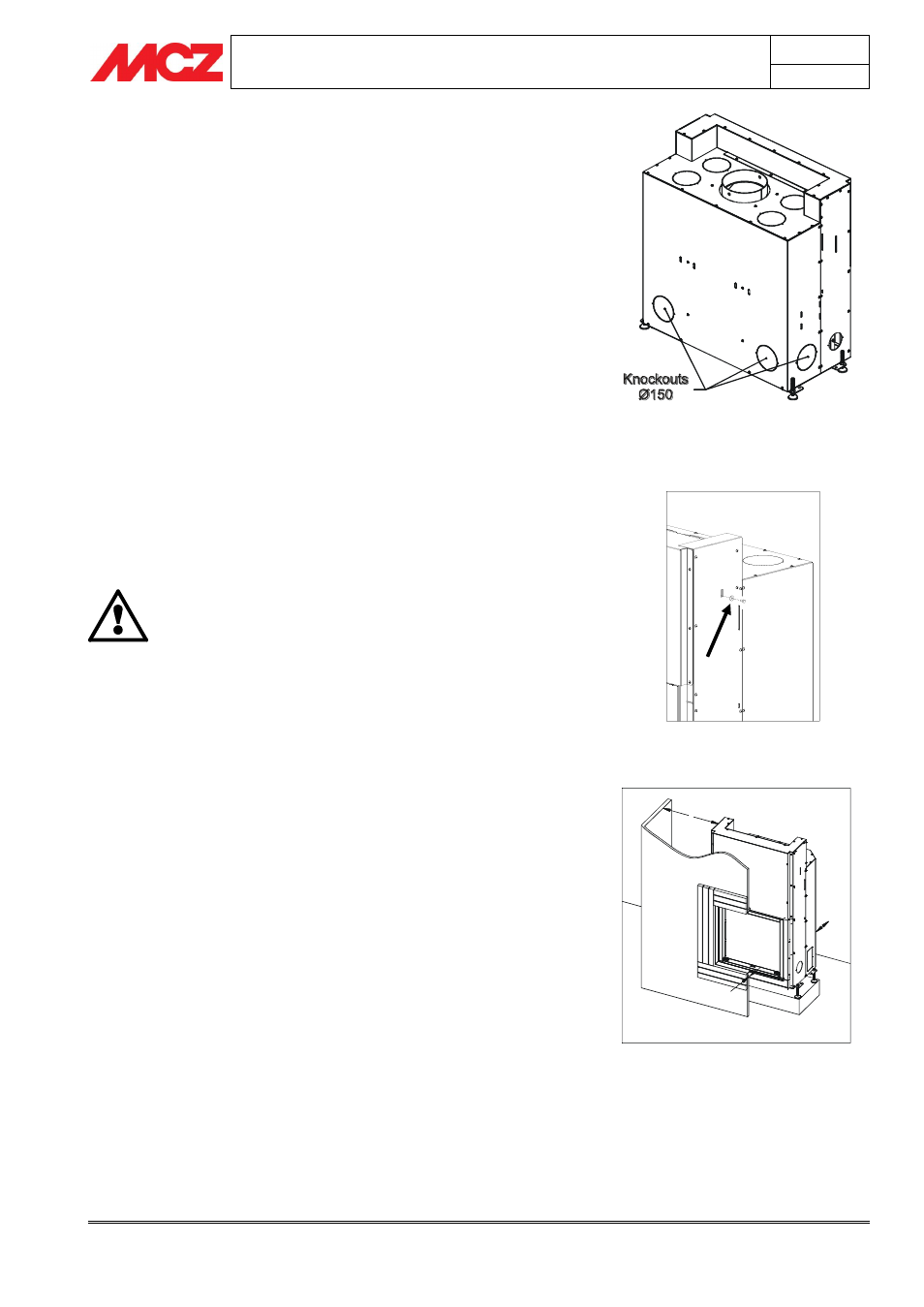
4.2.1. Natural convection (VN)
If it is decided to opt for this system, the knockout panels in the
sides and on the back of the unit (as shown in
figure 1
) must be
removed in order to facilitate heat exchange and air circulation.
The upper knockout panels are circular, Ø 150 mm.
At least two of
them should be opened and ducted for correct distribution of warm air.
To open the knockout panels, hit them with a rubber mallet and remove
the profile that detaches from the unit.
4.2.2. Forced convection (VF)
If you adopt this system, purchase the optional Comfort Air kit and
follow the instructions in
paragraph 5.3 “Installation of comfort air kit".
4.3. RELEASE OF COUNTERWEIGHTS
The fireplace stove is delivered with the sliding counterweights locked in
place. In this way, during shipping and handling, they will not strike and
damage the sliding parts, the door and the ceramic glass.
To release the counterweights and therefore also the door, remove the
screws as shown in
figure 2
from both sides of the fireplace stove.
Remove the screws that hold the counterweights only
after you have positioned the fireplace stove and to
ensure that the glass is in good condition.
DO NOT MOVE THE FIREPLACE STOVE WITHOUT THE
SCREWS THAT HOLD THE COUNTERWEIGHTS.
Damage caused by failure to observe this rule is the
responsibility of the client or his representative.
4.4. POSITIONING
The FORMA fireplace stove can be placed in a corner or along a wall.
You can customize with MCZ claddings or install them during
construction with materials that are resistant to high temperatures.
The fireplace stoves are self-supporting single-piece units that simplify
installation and do not require any additional support.
To make it easier to move the unit to its place of installation, MCZ
provides four swivel castors that make moving the fireplace stove easy
and convenient.
The four castors, which you will find in the fire mouth along with the
rest of the equipment, are to be installed in the provided holes, located
near the holes for the adjustment feet (figure 3b). Once the fireplace
stove is in place, the castors must be raised off the ground or removed,
so that the unit is stable on the floor.
Always evaluate the structural condition of the surface which
will take the weight, and always leave a minimum 5 cm
airspace between the stove and any walls.
Install dry the fire bed of the cladding leaving an opening of 1 cm
for the insulation.
(Figure 3a)
Figure 3a – Distance of unit from walls and from
cladding
Figure 2 – Screw to hold counterweights
Figure 1 – Forma Line knockout panels
5 cm
min.
5 cm
min.
1 cm