Connection to the flue pipe, Installation of cladding and hood liner – MCZ Forma Wood 115 User Manual
Page 24
INSTALLATION AND USE MANUAL
Chapter 4
page
24
Installation and assembly
Technical service – MCZ S.p.A. all rights reserved - Reproduction prohibited
Remember that:
All of the air intakes must be equipped with shutters than can
be controlled from the outside and that are equipped with
insect protection.
The air intake section is considered net, therefore the area of
any obstructions must be considered (mesh, etc.)
The filters or meshes need to be cleaned periodically to ensure
air can pass through them.
Do not for any reason obstruct the air intakes if the fireplace
stove or ventilation kit is in operation
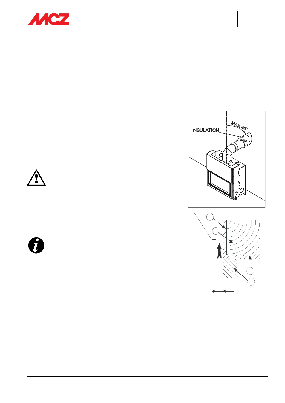
4.7. CONNECTION TO THE FLUE PIPE
We recommend connecting the stove to the flue pipe by means of pipes
and bends in aluminised steel, capable of withstanding the high
temperatures which are reached in that section of pipe, and of resisting
corrosion from the fumes. These connecting pipes are available on
request in various sizes (see our price list), and they simplify
installation, as they are assembled by fitting one into another.
(figure 7)
Any increase in the section of the connecting pipe
must start immediately above the hood of the
fireplace and not along the flue pipe section
When installation is complete, the smoke connection
must be insulated with ceramic fibre matting or
material that is resistant up to at least 600°C.
4.8. INSTALLATION OF CLADDING AND HOOD
LINER
BEFORE YOU START INSTALLING THE CLADDING OF
THE FIREPLACE STOVE, READ CHAPTER 6.2
“OPERATING TEST”
The fireplace stove and the parts of the cladding must be attached to
one another WITHOUT COMING INTO CONTACT WITH THE
STEEL STRUCTURE to prevent transmission of the heat to the marble
and/or stone, and to allow normal thermal dilation. Use care with wood
finsihes such as crossbeams or shelves.
We recommend making the hood liner in fire-resistant
plasterboard of 15/20 mm thickness, with a self-supporting frame in
galvanised profile, so as not put weight on components of the cladding
(such as wooden beams and marble architraves) which do not have a
load-bearing structure and to make it easy to work in the event of
future anomalies and/or maintenance.
Dry install the fire bed of the cladding, leaving an aperture of 1 cm
between the fireplace stove and the fire bed to provide insulation.
(figure 8)
THERMAL PROTECTION OF CROSSBEAM
1. Insulation applied or to be applied.
2. Wood beam
3. Marble or other material
1
1
2
3
10 mm
Figure 7 – Connection to the flue pipe
Figure 8 – Insulating a wooden beam