RISCO Group GT480 User Manual
Page 11
II
II
n
n
n
n
s
s
s
s
tt
tt
a
a
a
a
ll
ll
ll
ll
a
a
a
a
tt
tt
ii
ii
o
o
o
o
n
n
n
n
M
M
M
M
a
a
a
a
n
n
n
n
u
u
u
u
a
a
a
a
ll
ll
G
G
G
G
T
T
T
T
4
4
4
4
8
8
8
8
0
0
0
0
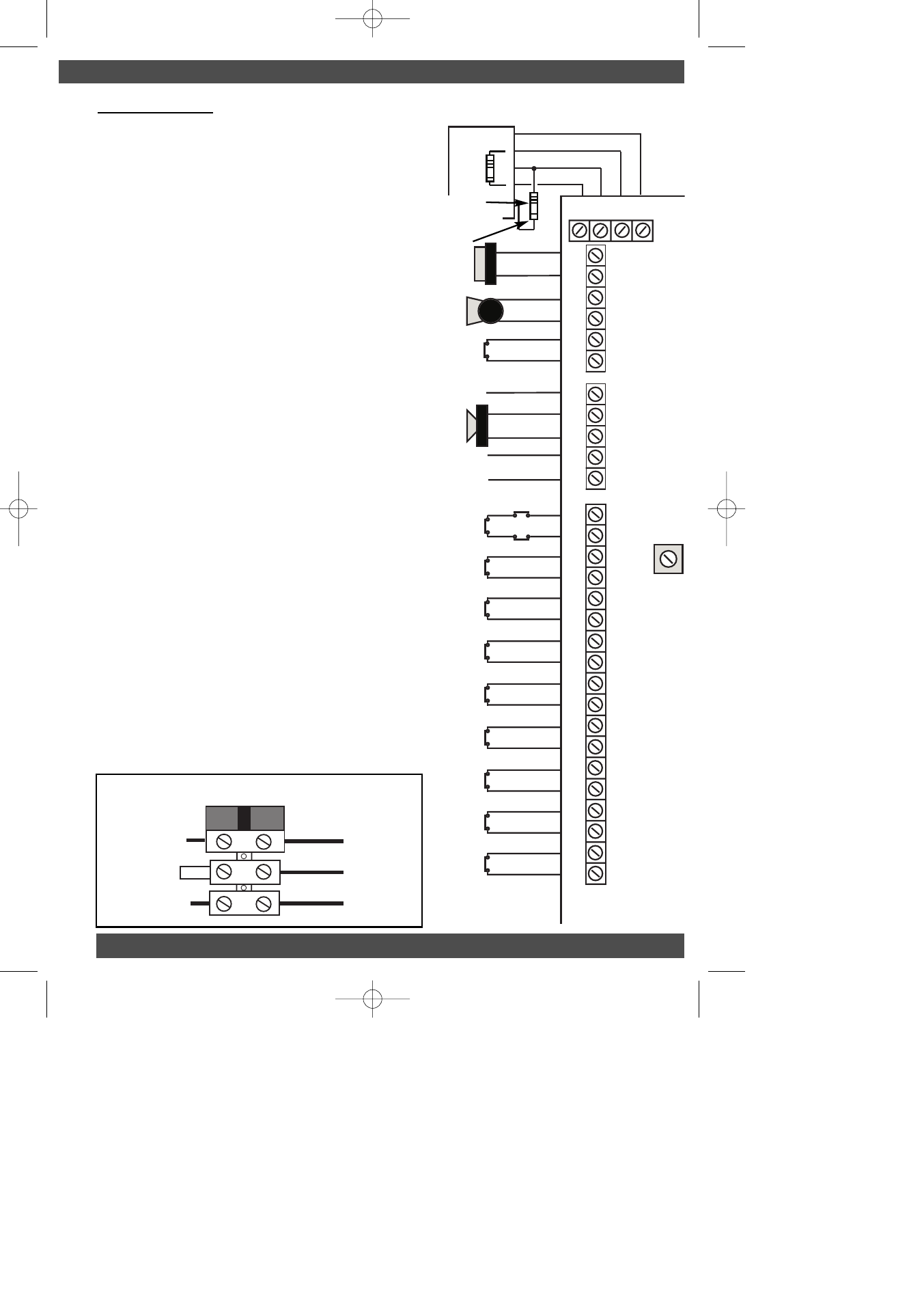
Wiring Notes
The 680 Ohm resistor (provided) must be
fitted across 12v & D1 at the last RKP in line.
Maximum current draw from the panel MUST
NOT EXCEED 1Amp*. (See Page 23 for further
information). This includes all Bells, Sounders,
Speakers, Detectors & RKPs etc. Battery
recharge current must also be taken into
consideration.
Max Output current for Strobe is 250mA.
Max Output current for Bell is 500mA.
Panel speaker volume may be adjusted via RV1
on the Control Panel.
Display contrast may be adjusted via RV1 on the
RKP.
PGM1 sink current is 50mA
PGM1 is pulled high 1K pull-up resistor
Minimum impedance for Speaker is 16 Ohm
in any speaker configuration.
Please refer to the Wiring Global Tampers section
for details of wiring multiple tampers.
Multiple detectors fitted to a single zone should
have the alarm contacts wired in series. Please
see detector wiring section for more details.
Any N/O devices such as pressure pads should
be wired across the Global Tamper and the zone
required. The zone terminals should remain
shorted.
When connecting the battery to the unit please
ensure correct polarity.
P
P
P
P
a
a
a
a
g
g
g
g
e
e
e
e
8
8
8
8
+ - + - + - + - + - + - + - + -
+ -
TMP
AZ1
AZ2
AZ3
AZ4
AZ5
AZ6
AZ7
AZ8
REMOTE KEYPA
D
D2 D1 0V 12V
D2 D1 0V 12V
680 Ohm
RKP
Strobe
+-
Bell
+-
Bell
Hold-
SAB
TMP
PGM1
+-
SPKR
AUX 12v
+-
N/C Bell Tamper
Programmable Output
for detectors requiring
switched signals
Aux Supply for
Detectors etc.
N/C Detection Circuit
N/C Detection Circuit
N/C Detection Circuit
N/C Detection Circuit
N/C Detection Circuit
N/C Detection Circuit
N/C Detection Circuit
N/C Detection Circuit
N/C Global Tamper
RV
1
Zone
2K2
Remove 2K2
if using Keypad
zones. (See Fig 5,
page 5).
Live
Brown
Earth
Green/Yellow
Neutral
Blue
Brown
Blue
200mA Anti-Surge
Fuse
From 3A Fused Spur
To Transformer
Earth
Tag
Fig. 7 Control Panel Connections
Fig. 8 Mains Terminal Block Connections
Also remove 2K2
if eurosec RKP
GardTec 480 ENG PR5832 Rev 115IN480IM B A5booklet.qxd 18/07/2007 20:35 Page 8