RISCO Group GT480 User Manual
Page 7
II
II
n
n
n
n
s
s
s
s
tt
tt
a
a
a
a
ll
ll
ll
ll
a
a
a
a
tt
tt
ii
ii
o
o
o
o
n
n
n
n
M
M
M
M
a
a
a
a
n
n
n
n
u
u
u
u
a
a
a
a
ll
ll
G
G
G
G
T
T
T
T
4
4
4
4
8
8
8
8
0
0
0
0
General Detector Wiring
We would strongly suggest that you adopt a colour scheme for the detector wiring of your
system. This will enable you to quickly determine the source of any problems that may occur.
The security industry does not have recommended colour schemes because of the nature of
the wiring, one suggested scheme is given below.
Red/Black.................... Power
Green.......................... Tamper
White........................... Tamper
Yellow/Blue.................. Alarm
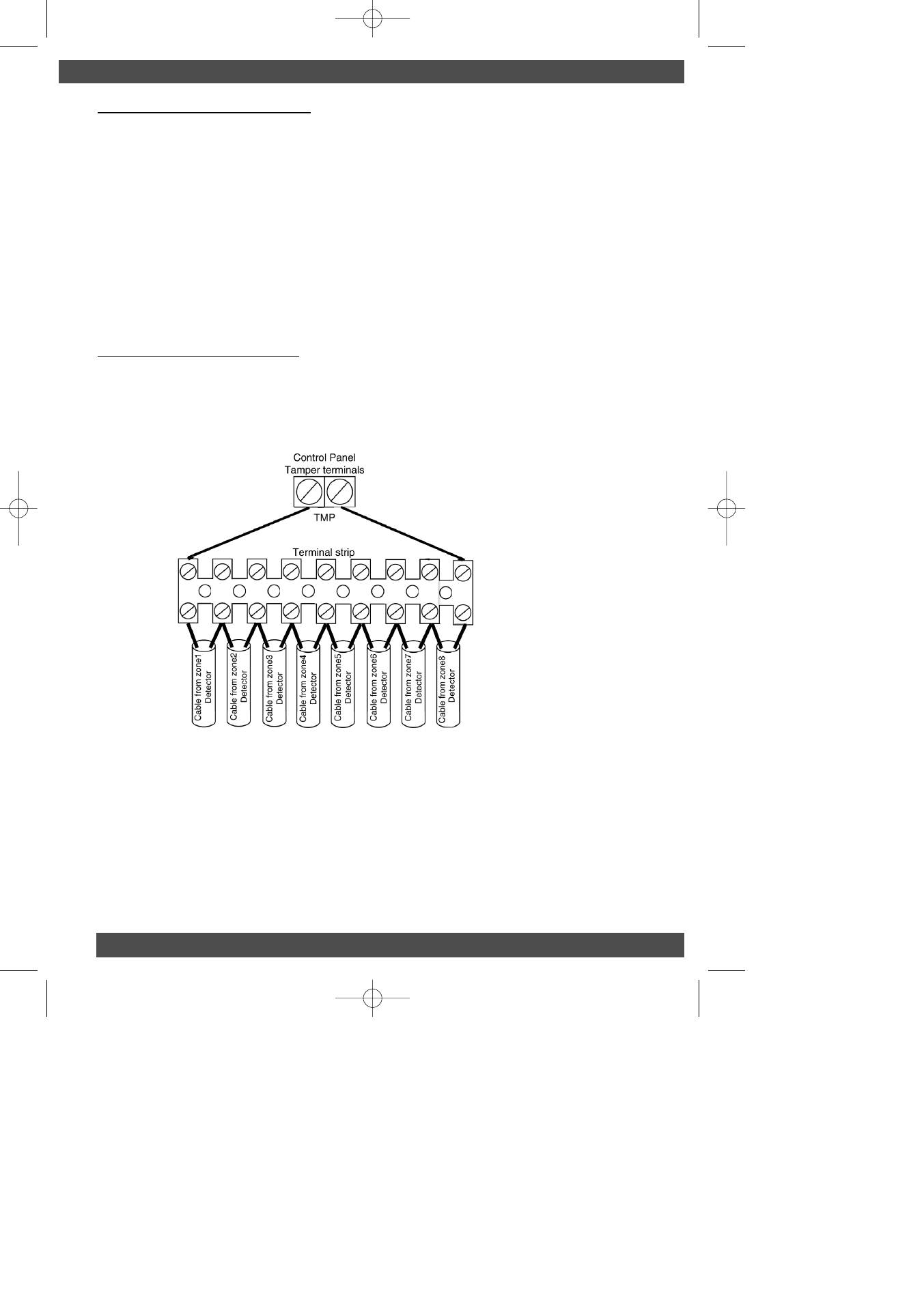
Wiring Global Tampers
One pair of tamper terminals is provided on the control panel PCB for tamper protection of the
zones. This is termed as a Global Tamper, one simple method of wiring Global Tampers is
shown in Fig. 1 below.
Fig. 1 Wiring Global Tampers
Wiring Contacts
Many types of contacts are available and fall in to two categories, surface or flush. The method
of operation is the same for both. One half of the contact is fitted to the door or window frame,
inside is a reed switch that is pulled together in the presence of a magnetic field. The other half
that is fitted to the opening section of the door or window contains the magnet. These devices
are referred to as normally closed (NC or N/C). The gap allowed for reliable operation will vary
(usually between 5mm & 20mm) dependant on the model used, you should check this
specification with your supplier before fitting.
In Figs. 2 & 3 we have used 5 screw surface contacts for clarity of the illustration.
P
P
P
P
a
a
a
a
g
g
g
g
e
e
e
e
4
4
4
4
GardTec 480 ENG PR5832 Rev 115IN480IM B A5booklet.qxd 18/07/2007 20:35 Page 4