Rose Electronics CrystalView Pro Fiber User Manual
Page 12
6
CRYSTALVIEW PRO FIBER
INSTALLATION AND OPERATIONS MANUAL
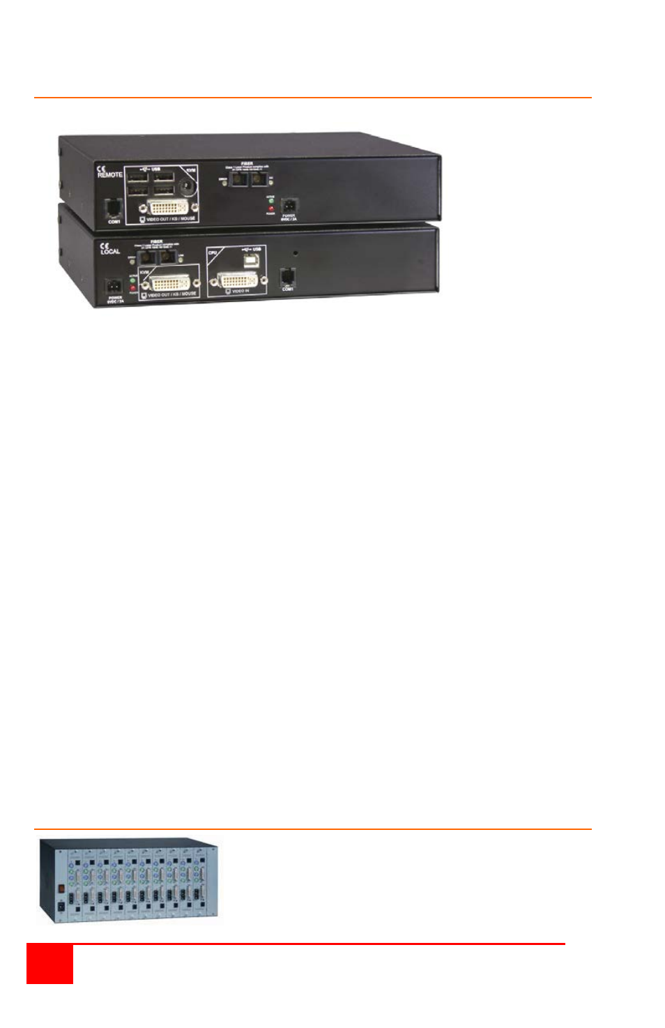
USB Model
Receiver
Transmitter
Figure 3. USB Model
Connectors:
Receiver
DVI-I – KVM stations video monitor connection.
USB – KVM stations keyboard and mouse connection
or USB compatible peripherals
Fiber – SC-type
4-pin square – Power
6-pin barrel – Auxiliary 5.0V USB power *
RJ11 – Programming (See Appendix C)
Transmitter
DVI-I – CPU video in connection
DVI-I – Video out connection
USB – CPU keyboard and mouse connections
(For local keyboard and mouse access on the dual model, connect a
keyboard and mouse directly to the computer’s USB ports or a USB
Hub)
SC-type – Fiber cable connector
4-pin square – Power
RJ11 – Programming (See Appendix C)
* For USB peripherals connected to the receiver that require a
power source between 100 – 500 ma max.
Rack Model
The rack model consists of 1 to 10
independent units mounted in a single
rack mountable chassis. Transmitters
and receivers can be installed in the same
chassis.