Figure 2-2. tma 4882-27 front and rear panels, Table 2-4. input/output pin assignments, Tma 4882-27 front and rear panels -7 – KEPCO TMA 4882-27 User Manual
Page 25: Input/output pin assignments -7, Le 2-4, See figure 2-2 ), Able 2-4 for pin, Ble 2-4, E 2-4 fo
Advertising
TMA 4882-27 021910
2-7
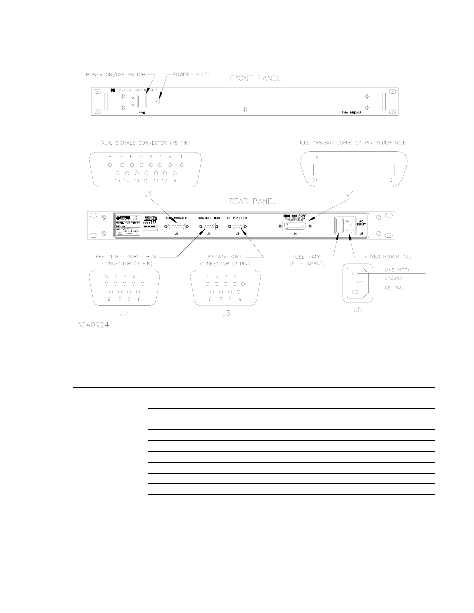
FIGURE 2-2. TMA 4882-27 FRONT AND REAR PANELS
TABLE 2-4. INPUT/OUTPUT PIN ASSIGNMENTS
CONNECTOR
PIN
SIGNAL NAME
FUNCTION
RS232-C
PORT
1
SGND
Signal Ground
2
RXD
Receive Data
3
TXD
Transmit Data
4
DTR
(not used)
5
SGND
Signal Ground
6
DSR
See Note 2.
7
RTS
See Notes 1 and 2.
8
CTS
See Note 1.
9
SGND
Signal Ground
NOTE 1
Jumper installed between CTS and RTS allows DIP switches to configure RS 232
port. Jumper NOT installed established default RS 232 configuration (9600 baud,
Echo on, XON off).
NOTE 2
Jumper installed between DSR and RTS allows secondary GPIB addressing if SCPI
mode 0 (see Table 2-2) is selected
Advertising