Max ii cpld epm2210 system controller, Max ii cpld epm2210 system controller –6 – Altera Cyclone III LS FPGA Development Board User Manual
Page 14
2–6
Chapter 2: Board Components
MAX II CPLD EPM2210 System Controller
Cyclone III LS FPGA Development Board Reference Manual
© October 2009 Altera
Corporation
MAX II CPLD EPM2210 System Controller
The board utilizes the EPM2210 System Controller, an Altera MAX
II CPLD, for the
following purposes:
■
FPGA configuration from flash memory
■
Power consumption monitoring
■
Virtual JTAG interface for PC-based GUI
■
Control registers for clocks
■
Control registers for remote system update
■
Anti-Tamper example design
1
The development kit includes the anti-tamper example design in the
<install_dir>\kits\cycloneIIILS_3cls200_fpga\examples\max2\at_example\
readme_at_example.txt
directory.
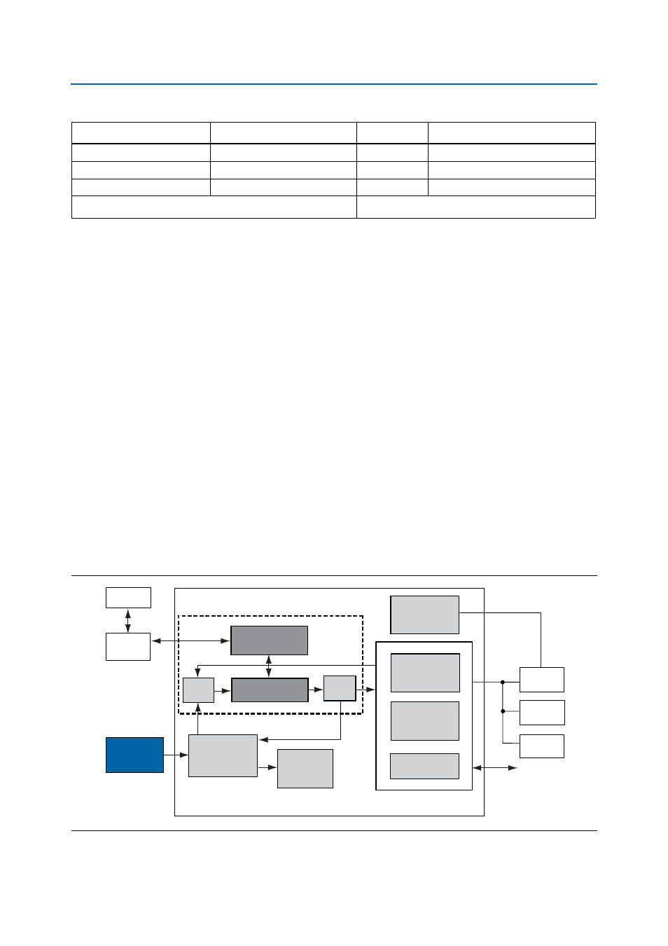
illustrates the MAX II CPLD EPM2210 System Controller's functionality
and external circuit connections as a block diagram.
LEDs
1.8-V CMOS
5
1 INIT_DONE
Clocks or Oscillators
1.8-V / 2.5-V CMOS + LVDS
5
2 differential clock input, 1 clock input
EEPROM
2.5-V CMOS
2
—
Device I/O Total:
390
Note to
:
(1) The LCD signals are multiplexed with HSMB_D[65:75] and therefore not included in the total pin count.
Table 2–4. Cyclone III LS Device Pin Count and Usage (Part 2 of 2)
Function
I/O Standard
I/O Count
Special Pins
Figure 2–3. MAX II CPLD EPM2210 System Controller Block Diagram
Information
Register
Embedded
Blaster
MAX-II
Power
Calculations
SLD-HUB
PFL
Power
Measurement
Results
Virtual-JTAG
PC
3CLS
LTC2418
Controller
FLASH
Decoder
Encoder
GPIO
JTAG Control
SSRAM
Control
Register
Anti-Tamper
Example Design