Status elements, Fpga programming over external usb-blaster –16, Status elements –16 – Altera Cyclone III LS FPGA Development Board User Manual
Page 24: Illuminated, Table 2–8
2–16
Chapter 2: Board Components
Configuration, Status, and Setup Elements
Cyclone III LS FPGA Development Board Reference Manual
© October 2009 Altera
Corporation
FPGA Programming over External USB-Blaster
The JTAG programming header provides another method for configuring the FPGA
(U15) using an external USB-Blaster device with the Quartus II Programmer running
on a PC. The external USB-Blaster is connected to the board through the JTAG
connector (J8). Removing all shunt jumpers from the JTAG chain header (J11) removes
all devices from the JTAG chain so that the FPGA is the only device on the chain. To
add the MAX
II CPLD EPM2210 System Controller to the JTAG chain, place a shunt
on the JTAG chain header (J11) pin 1 and 2.
f
For more information on the following topics, refer to the respective documents:
■
Board Update Portal, re
.
■
PFL design, refer to the
.
■
PFL megafunction, refer to
Status Elements
The development board includes status LEDs. This section describes the status
elements.
lists the LED board references, names, and functional descriptions.
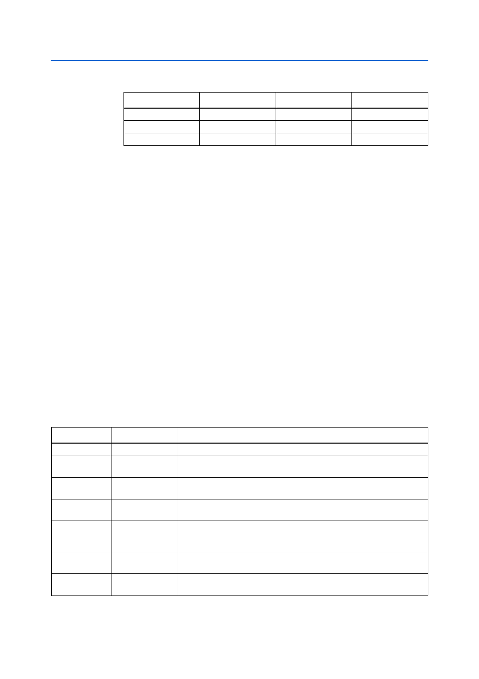
Table 2–8. PGM Configure Push-Button Switch (S8) LED Settings
PGM_LED0
PGM_LED1
PGM_LED2
Design
ON
OFF
OFF
Factory hardware
OFF
ON
OFF
User hardware 1
OFF
OFF
ON
User hardware 2
Note to
(1) ON indicates a setting of ’0’ while OFF indicates a setting of ’1’.
Table 2–9. Board-Specific LEDs (Part 1 of 2)
Board Reference
LED Name
Description
D3
Power
Blue LED. Illuminates when 12-V power is active.
D7
JTAG_AT_SEL
Green LED. Illuminated when the default JTAG chain is broken and the MAX II
EPM2210 System Controller has control of the FPGA JTAG pins.
D13
CONF DONE
Green LED. Illuminates when the FPGA is successfully configured. Driven by the
MAX II CPLD EPM2210 System Controller.
D14
INIT DONE
Green LED. Illuminates when the FPGA is successfully configured and is in user
mode. This setting must be selected in the Quartus II programmer.
D11
LOAD
Green LED. Illuminates when the MAX II CPLD EPM2210 System Controller is
actively configuring the FPGA. Driven by the MAX II CPLD EPM2210 System
Controller.
D10
Error
Red LED. Illuminates when the MAX II CPLD EPM2210 System Controller fails to
configure the FPGA. Driven by the MAX II CPLD EPM2210 System Controller.
D12
FACTORY
Green LED. Illuminates when the factory image is loaded to the FPGA. Driven by
the MAX II CPLD EPM2210 System Controller.