Altera Cyclone III LS FPGA Development Board User Manual
Page 36
2–28
Chapter 2: Board Components
Components and Interfaces
Cyclone III LS FPGA Development Board Reference Manual
© October 2009 Altera
Corporation
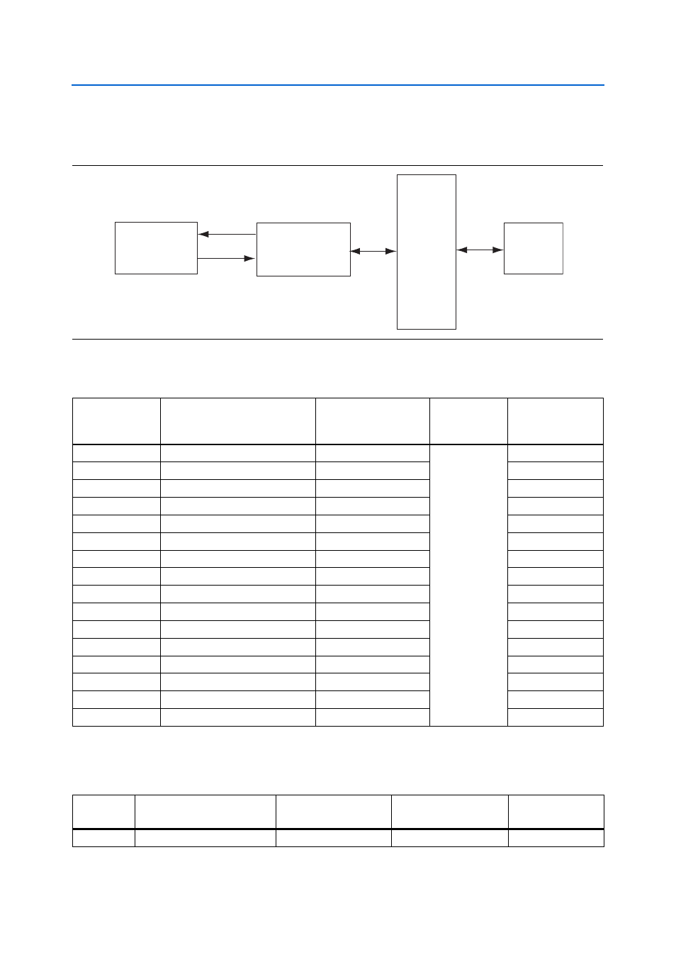
shows the RGMII interface between the FPGA (MAC) and Marvell 88E1111
PHY.
lists the Ethernet PHY interface pin assignments.
lists the Ethernet PHY interface component reference and manufacturing
information.
Figure 2–8. RGMII Interface between FPGA (MAC) and Marvell 88E1111 PHY
10/100/1000 Mbps
Ethernet MAC
Marvell 88E1111
PHY
Device
Transformer
RJ45
RGMII Interface
TXD[3:0]
RXD[3:0]
Table 2–32. Ethernet PHY Pin Assignments, Signal Names and Functions
Board Reference
Description
Schematic Signal Name
I/O Standard
Cyclone III LS
Device
Pin Number
U24.8
RGMII transmit clock
ENET_GTX_CLK
2.5-V
AC14
U24.23
Management bus interrupt
ENET_INTn
N23
U24.25
Management bus control
ENET_MDC
AH12
U24.24
Management bus data
ENET_MDIO
AH27
U24.28
Device reset
ENET_RESETn
AF24
U24.2
RGMII receive clock
ENET_RX_CLK
AG13
U24.94
RGMII receive control
ENET_RX_DV
AH15
U24.95
RGMII receive data
ENET_RXD0
AF13
U24.92
RGMII receive data
ENET_RXD1
AB14
U24.93
RGMII receive data
ENET_RXD2
AH13
U24.91
RGMII receive data
ENET_RXD3
AG8
U24.9
RGMII transmit control
ENET_TX_EN
AF6
U24.11
RGMII transmit data
ENET_TXD0
AE14
U24.12
RGMII transmit data
ENET_TXD1
AD12
U24.14
RGMII transmit data
ENET_TXD2
AB17
U24.16
RGMII transmit data
ENET_TXD3
AC6
Table 2–33. Ethernet PHY Component Reference and Manufacturing Information
Board
Reference
Description
Manufacturer
Manufacturing
Part Number
Manufacturer
Website
U24
Ethernet PHY BASE-T device
Marvell Semiconductor
88E1111-B2-CAAIC000