Connecting the power supply – Applied Motion ST10-C-CE User Manual
Page 21
21
ST5/10-Si,-Q,-C, IP Hardware manual
920-0004 Rev. F
6/10/14
Connecting the Power Supply
If you need information about choosing a power supply, please read Choosing a Power Supply located
elsewhere in this manual.
Connect the motor power supply “+” terminal to the driver terminal labeled “V+”. Connect power supply
“-” to the drive terminal labeled “V-”. Use 18 or 20 gauge wire. The ST drives contain an internal fuse that
connects to the power supply + terminal. This fuse is not user replaceable. If you want to install a user
servicable fuse in your system install a fast acting fuse in line with the + power supply lead. Use a 7 amp
fast acting fuse for the ST5 and ST10 drives.
The green ground screw on the corner of the chassis should be connected to earth ground.
Be careful not to reverse the wires. Reverse connection will destroy your driver, void your
warranty and generally wreck your day.
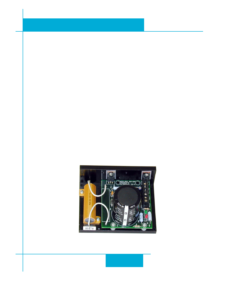
If you plan to use a regulated power supply you may encounter a problem with regeneration. If you rapidly
decelerate a load from a high speed, much of the kinetic energy of that load is transferred back to the power
supply. This can trip the overvoltage protection of a switching power supply, causing it to shut down. We
offer the RC050 “regeneration clamp” to solve this problem. If in doubt, buy an RC050 for your first instal-
lation. If the “regen” LED on the RC050 never flashes, you don’t need the clamp.
RC050 Regen Clamp