Connecting input signals, Connector pin diagram, Connector pin diagram in/out1 (db-25) connector – Applied Motion ST10-C-CE User Manual
Page 25
25
ST5/10-Si,-Q,-C, IP Hardware manual
920-0004 Rev. F
6/10/14
Connecting Input Signals
The ST drives have three types of inputs:
• high speed digital inputs for step & direction commands or encoder following, 5 volt logic
• digital inputs for other signals, 12 - 24 volt logic
• analog inputs for analog speed and positioning modes
All drives include eight digital inputs and two analog inputs.
• CW & CCW Limit: can be used to inhibit motion in a given direction, forcing the motor and load to travel
within mechanical limits. Can be configured for active closed, active open or not used.
• IN1/STEP & IN2/DIR: digital signals for commanding position. Quadrature signals from encoders can
also be used. These inputs can also be connected to sensors, switches and other devices for use with Q and
Si™ commands such as Wait Input, Seek Home, Feed to Sensor, If Input and others.
• IN3,4,5,6: software programmable inputs can be used for motor enable, alarm reset or jogging. These in-
puts can also be connected to sensors, switches and other devices for use with Q and Si™ Wait Input, Seek
Home, Feed to Sensor, If Input and other commands.
• Analog In: analog velocity or position command signal. Can be configured for 0-10V, 0-5V, ±10V or ±5V,
with or without offset.
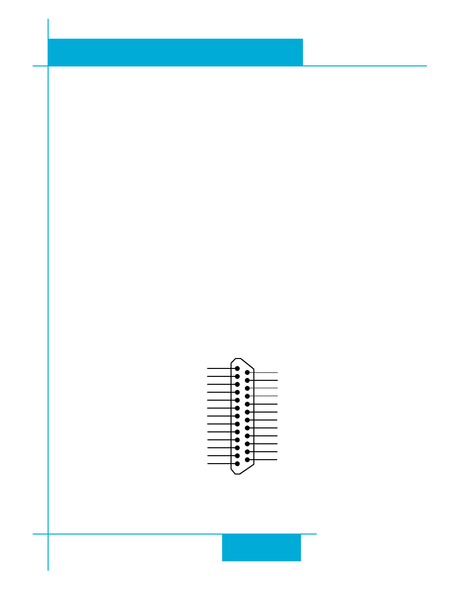
Connector Pin Diagram
IN/OUT1 (DB-25) Connector
Front View
X COMMON
X3 / Enable
X5 / CWJOG
X4 / Alarm Reset
Analog IN2
Analog IN1
X2 / DIR-
X2 / DIR+
X1 / STEP +
X1 / STEP -
GND
GND
+5V OUT
Y COMMON
Y3 / FAULT
Y2 / MOTION
Y1 / BRAKE
� �
� �
� �
� �
� �
� �
� �
� �
� �
�
�
�
�
�
�
�
�
�
� �
� �
� �
� �
� �
� �
� �
X6 / CCWJOG
IN/OUT
X8/CCWLIMIT+
X8/CCWLIMIT-
X7/CWLIMIT-
X7/CWLIMIT+
Y4-
Y4+