1 power circuit, 2 external isolation and protection elements, 3 auxiliary control voltage – CIRCUTOR FRE Series User Manual
Page 11: 4 earth cable connection, N 5.3.3), On 5.3.3
FRE / FRES
11 / 20
5.3.1 Power circuit.
•
Connect input terminals L1, L2 and L3 (power circuit) to the grid using proper sized cable in
accordance with the LVR. Generally, the cables of the phases follow the following colour code: L1
(black), L2 (brown), L3 (grey). If an auxiliary voltage is required to supply some auxiliary elements,
the supply is obtained from a suitable transformer or auto-transformer.
•
To determine the size of the phase cables, the maximum nominal current I
max
shown on the
equipment's label and a transient overload of up to 1.5 times I
max
must be taken into account.
5.3.2 External isolation and protection elements
•
In case the capacitor bank with filters does not have an internal switch or circuit breaker, it must be
connected to a line with an external switch or circuit breaker.
The protection elements, isolation switches and/or switches that are added
externally to the capacitor bank must be of a minimum size to withstand a current
1.5 times greater than what is indicated on the label
If an earth leakage protection for the capacitor bank is installed, its sensitivity and
trip delay must be adjustable.
•
For static capacitor banks with filters equipped with a standard regulator that measures the current in
one single phase, we advise installing the current transformer (CT) in the phase connected to L1
(black cable). The CT secondary outputs, S1 and S2, must be connected to the terminals with the
same name on the main cabinet. For more details about the connection of the CT, see 5.3.5
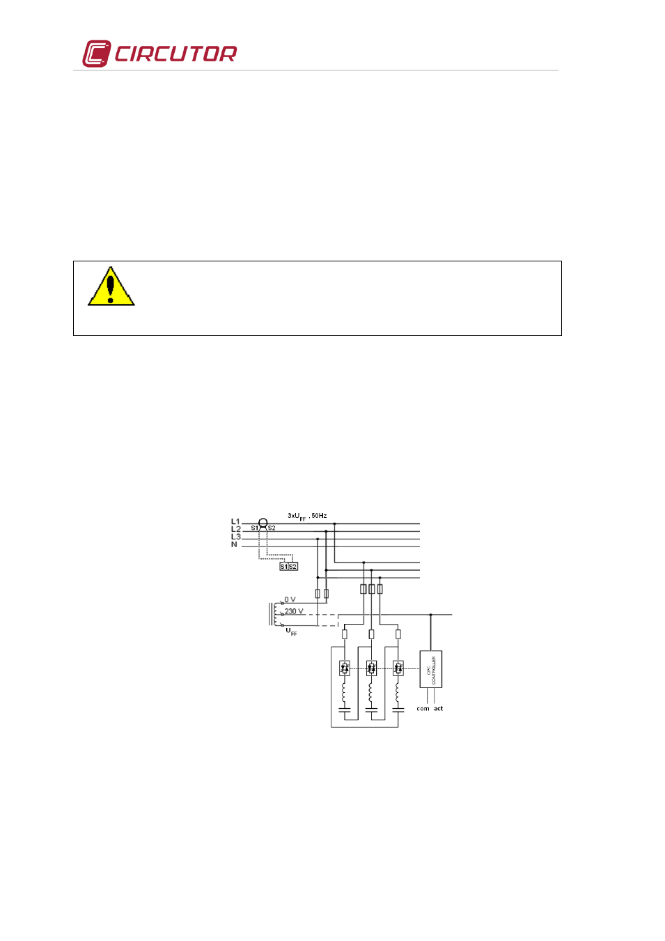
5.3.3 Auxiliary control voltage.
•
The auxiliary control circuits include those related to the power supply of the CPCxx controllers and
other control or protection devices and ventilation units. The CPC controllers, up to 400 V
ac
, usually
are supplied at 400 V
ac
from phase to phase voltage. In other applications using a voltage above 440
V
ac
and up to 690 V
ac
, the CPC must be supplied from an auxiliary source, usually obtained from a
suitable transformer or auto-transformer. In such case the label will indicate U
aux
/f … internal.
•
Fig. 5-1.- Auxiliary supply by means of autotransformer
5.3.4 Earth cable connection
Connect the earth terminal of the FRE or FRES equipment, located inside the equipment cabinet(see Fig.
4-3) to the exterior earth connection. The earth cable section will be selected in accordance with the
admissible current limits established in the Low Voltage Directive or in the National code of the country
where the filter is installed.