5 connecting the current transformer (ct) – CIRCUTOR FRE Series User Manual
Page 12
FRE / FRES
12 / 20
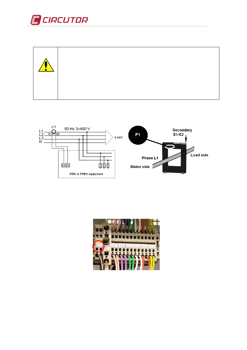
5.3.5 Connecting the current transformer (CT)
An external current transformer (CT) must be installed to measure the total
load current plus that of the filter (see Fig. 5-2).
The standard transformer must have a nominal secondary output of 5A.
We recommend connecting the CT to phase L1. The primary indications P1 - P2
must be placed in the direction grid to load (see Fig. 5-2). Terminals S1-S2, must be
connected to terminals with the same name on cabinet terminal strip (see Fig. 5-2).
Avoid the flow of current through the CT primary before closing the secondary to
terminals S1 and S2 in the cabinet. If the CT must be installed while the installation is
working, make a short-circuit between S1 and S2 while they are not connected to the
capacitor bank terminals.
•
The current rating of the CT primary winding must be equal to or slightly greater than the size of the
installation's mains switch. Therefore, the CT must be able to measure the maximum expected
current of the loads being compensated.
Fig. 5-2 .- Installation of the current transformer (CT) (external)
•
The connection point of the CT for a capacitor bank that compensates an entire installation is after
the installation's mains switch.
•
To prevent excessive attenuation of the signal, the minimum cross section of secondary cables
(terminals S1, S2) should be 2.5 mm2.
Fig. 5-3 .- CT connection terminals
•
Once the cables are installed, disconnect the jumper connecting terminals S1 and S2 inside the
capacitor bank (see Fig. 5-4)