4 environmental conditions, Nvironmental, Onditions – CIRCUTOR FRE Series User Manual
Page 17: N table7-4
FRE / FRES
17 / 20
- Check that the steps connect and disconnect properly
- Check that there is no consumption in any phase with the step disconnected. If there is
consumption this means that some of the thyristors are defective.
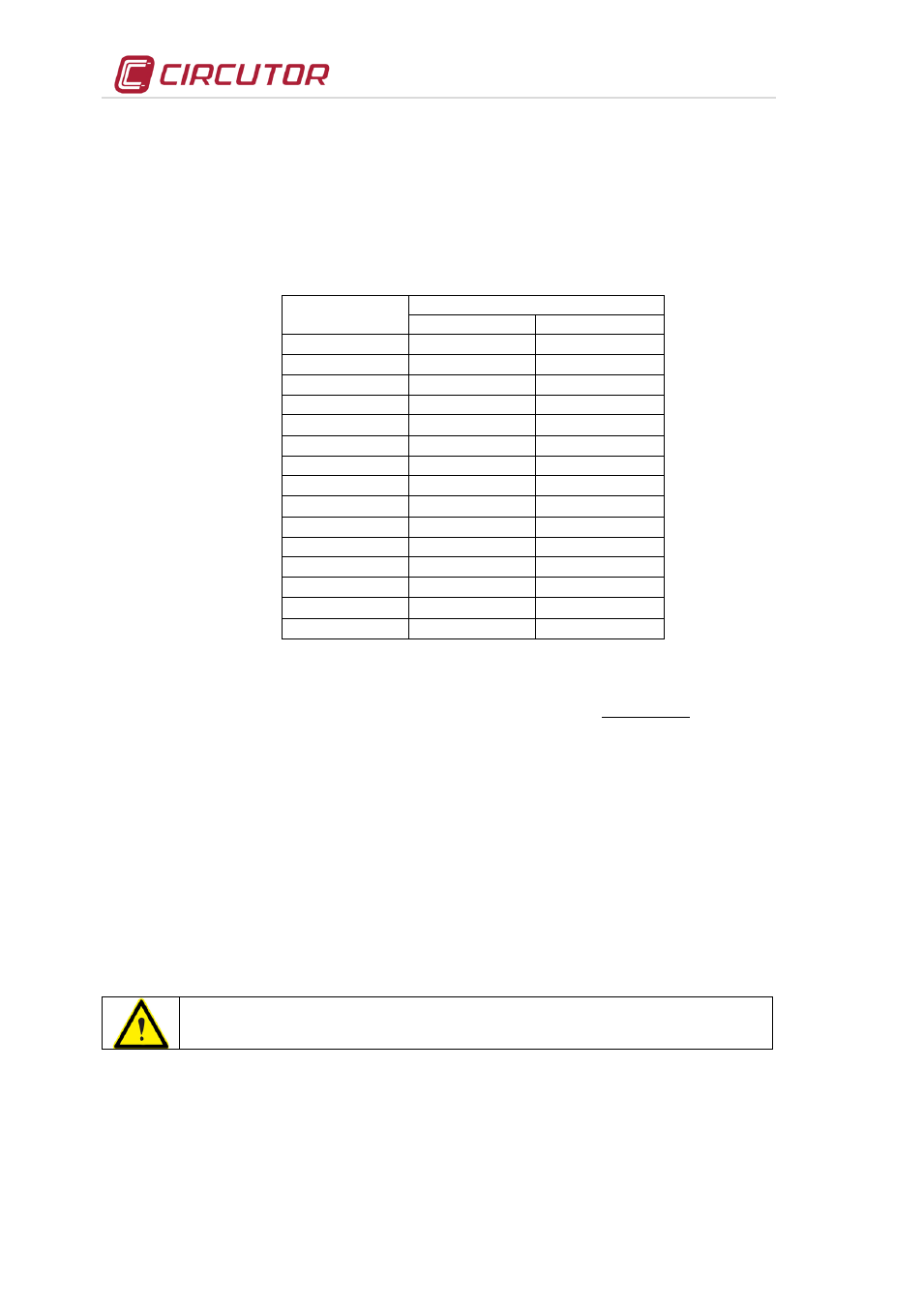
- Check the consumption of the different steps, in each phase. The normal values are shown in
Table 7-4.- Nominal consumption of the LC steps of an FRE or FRES filter
POWER
CURRENT
230V
400V
I
n
I
n
2.5 kvar
6.28 A
3.6 A
5 kvar
12.56 A
7.2 A
7.5 kvar
18.85 A
10.8 A
10 kvar
25.12 A
14.4 A
12.5 kvar
31.41 A
18 A
15 kvar
37.7 A
21.6 A
20 kvar
50.24 A
28.8 A
25 kvar
62.82 A
36 A
30 kvar
75.4 A
43.2 A
40 kvar
100.48 A
57.6 A
50 kvar
125.64 A
72 A
60 kvar
150.8 A
86.4 A
70 kvar
175.92 A
101.1 A
80 kvar
200.96 A
115 A
- Check the voltage on all of the reactor's windings (input - output of the same winding, not
between phases). The voltage depends on the filter's p% factor (see label on the equipment), in
accordance with the following formula:
%)
p
100
(
%
p
.
577
,
0
V
V
)
phase
phase
(
MAINS
L
−
=
−
For example, in the case of the 400V grid and p%=7, V
L
=17.38V. For the 400V grid and p%=14,
V
L
=37.57V. For other line voltages, the V
L
value is proportional to the line voltage.
NOTES:
•
When the consumption of the steps is 25% less than that stated in Table7-4 and the voltage is within
the tolerance limits, this is a sign of degradation in the capacitors. These must be replaced with a
suitable spare part if these symptoms are detected in a step.
•
When the consumption of the steps is 10% more than the values stated in Table7-4, this can be
caused by the presence of resonances. If this is detected, measure the grid's voltage THD (it must be
under 5%) or check the filter's tuning frequency.
•
If the voltage drop in a reactor deviates from the values stated in this section, check the reactor. This
phenomenon can be caused by the presence of a resonance.
7.3.3 PF regulator checkings.
Refer to the manual of the specific regulator used in the capacitor bank. This
manual is always supplied with the capacitor bank.
•
Make sure that there are no damaged segments on the display (abnormal brightness).
•
Make sure that regulator's keyboard is working properly:
- Enter Setup and check the adjusted values
- Force the manual connection and disconnection of a step.
7.4 Environmental Conditions:
•
Check that the maximum environmental conditions listed in section 4.3 are observed