Ests once the capacitor bank is connected and the, Regulator has been adjusted – CIRCUTOR FRE Series User Manual
Page 14
FRE / FRES
14 / 20
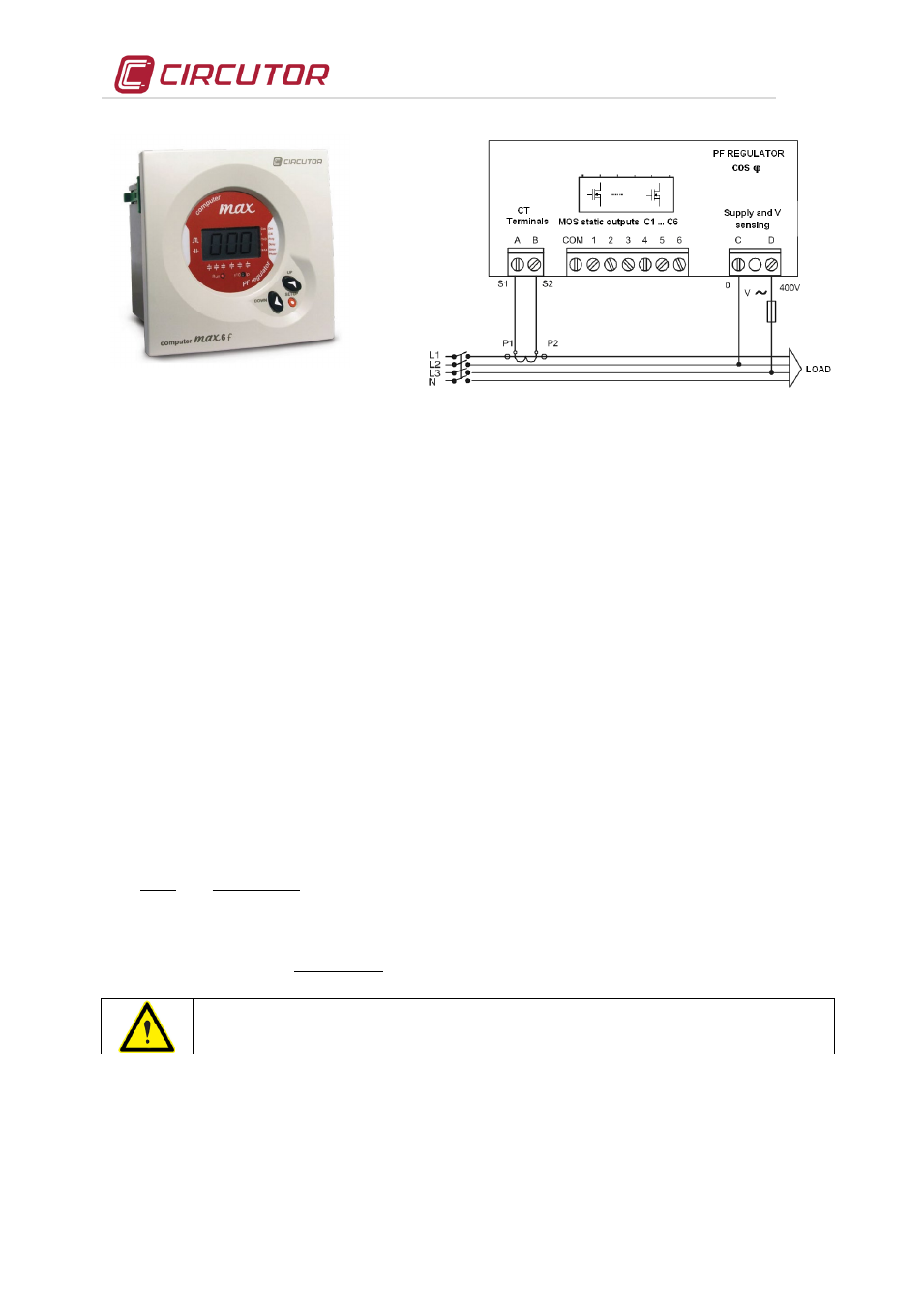
Fig. 6-1 .- Computer Max f Regulator
(Picture provided as an example. It may not coincide
with the model used on your unit).
Fig. 6-2 .- Standard connection of a regulator with a
single CT
(3 current transformers will be used when Computer + is
used. See the specific manual of the Computer + regulator)
•
Once ensured that the regulator is properly connected, set-up the regulator parameters according to
the installation you are attempting to compensate. For this, follow the regulator's instructions manual
included in the static filter documentation.
6.3 Tests once the capacitor bank is connected and the PF regulator has been adjusted
•
After start-up, make sure that the equipment is operating correctly. A sign of proper operation after
the regulator's reaction time has passed is a cosϕ indication close to 1. In addition, the reactive
energy meter must stop.
•
Check that the power supply voltage does not exceed the nominal value +10% (IEC 60831-1)
•
Check the current absorbed by each LC group of the filter. Under normal working conditions, it must
be close to the nominal values (see Table7-4) and never more than 1.3 times this value continuously.
Continuous consumption over the nominal value may be caused by the presence of harmonics in the
grid or an excessively high power supply voltage. Both circumstances are harmful for capacitors and
the filter reactors.
•
In accordance with the IEC 60831-1 Standard, the capacitor is prepared to operate at the permanent
voltage assigned and with an overvoltage of up to 10% during 8 hours every 24 hours.
•
NOTE: For capacitor banks with filters, the capacitor's voltage exceeds the grid voltage by a % that is
approximately equal to the filter's overvoltage factor (p%). In fact, the capacitor's real overvoltage is
%)
p
100
(
%
p
.
100
%
V
V
RED
C
−
=
∆
•
To check the filter's correct tuning, make sure that the voltage on the terminals of each winding of the
reactor is
%)
p
100
(
%
p
.
100
.
V
V
MAINS
L
−
=
Check the working temperature of the capacitors and reactors after they have been
operating for 24 hours. The capacitor case must be under 40 ºC. The housing of reactors
can reach temperatures of about 60 ºC