AMETEK Ls Series User Manual
Page 101
User Manual
Lx / Ls Series
97
6.3.1 Measurement Cal - AC
AC Volt Full-scale:
Program the output to 300 Volt AC and 400 Hz. Close the output
relay. Go to the MEASUREMENT CALIBRATION screen. Enter
the actual AC output voltage for the MVOLT FS parameter and
press the ENTER key. Save this value by pressing the
ENTER key.
AC Current Full-scale:
Calibrate the measurement current under a constant current
condition or a voltage fault may be generated. Apply a load to
the output. Program the output to 120 volts on the 150 volt
range and 400 Hz. Observe the actual output current and enter
this value for the MCURR FS parameter. Press the ENTER
key. Save this value by pressing the ENTER key.
6.3.2 Single and Three Phase Modes
As indicated earlier, for 3-Phase power system, repeat the preceding steps for the Phase B and
C outputs. The order in which the outputs for each phase are calibrated is not important.
Press the PHASE key to select each output to be calibrated. Monitor the output of the respective
phase by moving the HI input of the Digital Multimeter and the current shunt as needed. The LO
input should remain connected to the common LO of the sense connector.
The current measurement calibration for Phase A (ø1) should be done in both single and three
phase modes as separate calibration coefficients apply to each phase mode. Voltage
measurement calibration for phase A (ø1) can be done in either phase mode.
6.4 Output Calibration
The output calibration is performed automatically when the measurement calibration takes place.
As such, there is no need to perform this calibration again. The output calibration coefficients
may be viewed by selecting the OUTPUT CAL screen.
Output gain is set at the factory and the output calibration coefficients are pre-set. They is no
need to change the factory default settings unless any of the following conditions occurs:
1. Replacement of one or more amplifiers as a result of a service action.
2. Replacement of the current limit board. (CI P/N 7004-703-1)
3. Replacement of the controller board. (CI P/N 7004-708-1)
If the output gains are found to be out of tolerance, they need to be adjusted. This requires
removal of the top cover and should only be done by qualified service personnel. In that case,
refer to the non-routine gain calibration section.
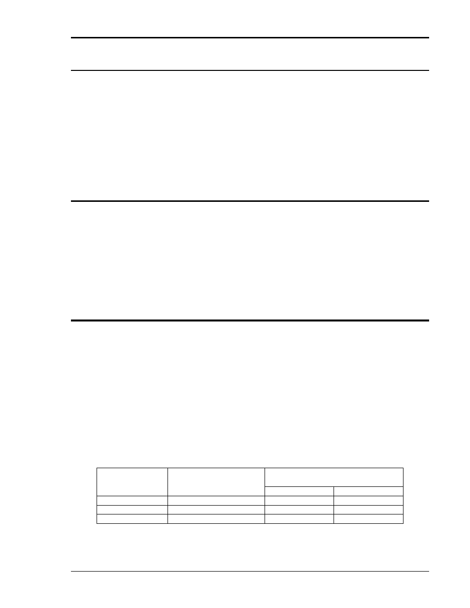
The factory output calibration coefficients are shown in the table below.
Output
Phase
Current Limit Board
Adjustment Pots
OUTP CAL value
Standard
-HF option
A or 1
R1
450
450
B or 2
R2
450
450
C or 3
R3
450
450
Table 6-3: Output Calibration Coefficients - Factory Defaults.