2 jumpers setting and connectors – Aplex Technology ACS-2120 User Manual
Page 14
ACS-2120 User Manual
14
2.2 Jumpers Setting and Connectors
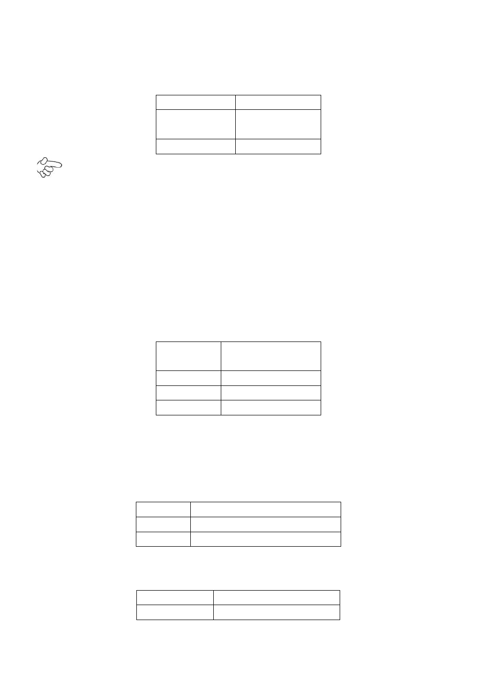
1. JCLR_CMOS:
(2.0mm Pitch 1x3 Pin Header)CMOS clear jumper, CMOS clear
operation will permanently reset old BIOS settings to factory defaults.
JCLR_CMOS
CMOS
CLOSE 1-2
NORMAL
(default)
CLOSE 2-3
Clear CMOS
Procedures of CMOS clear:
5.4.1.1 Turn off the system and unplug the power cord from the power outlet.
5.4.1.2 To clear the CMOS settings, use the jumper cap to close pins 2 and 3 for about
3 seconds then reinstall the jumper clip back to pins 1 and 2.
5.4.1.3 Power on the system again.
5.4.1.4 When entering the POST screen, press the <F1> or <DEL> key to enter CMOS
Setup Utility to load optimal defaults.
5.4.1.5 After the above operations, save changes and exit BIOS Setup.
2. JVCCIO:
(2.0mm Pitch 1x3 Pin Header) PC104+ port voltage selection jumper,select
voltage for PCI-104 Plus device.
The default for this jumper is
“all open”, meaning
the user must select the voltage to be used.
JVCCIO
PC104+ VCCIO
Voltage
CLOSE 1-2
+3.3V
CLOSE 2-3
+5V
all Open
(Default)
3. BZ:
onboard buzzer.
4. JCOM6:
(2.0mm Pitch 1x3 Pin Header) COM6 setting jumper, pin 1~3 are used to
select signal out of pin 10 of COM6 port.
JP1 Pin#
Function
Close 1-2 COM6 Pin10=+5V (default)
Close 2-3
COM6 Pin10=+12V (option)
5. JP2:
(2.0mm Pitch 1X2 Pin Header), ATX Power and Power auto on setting jumper.
JP2
Mode
Open
ATX Power Mode