Aplex Technology ACS-2120 User Manual
Page 20
ACS-2120 User Manual
20
CRT_GREEN
3
4
Ground
CRT_BLUE
5
6
NC
CRT_R_HSYN
C
7
8
CRT_PU_DDC_DAT
CRT_R_VSYN
C
9
10
CRT_PU_DDC_CLK
NC
11
12
NC
+12V
13
14
Ground
+12V
15
16
Ground
19. CPU SCREW HOLES:
Four screw holes for fixed CPU Cooler assemble.
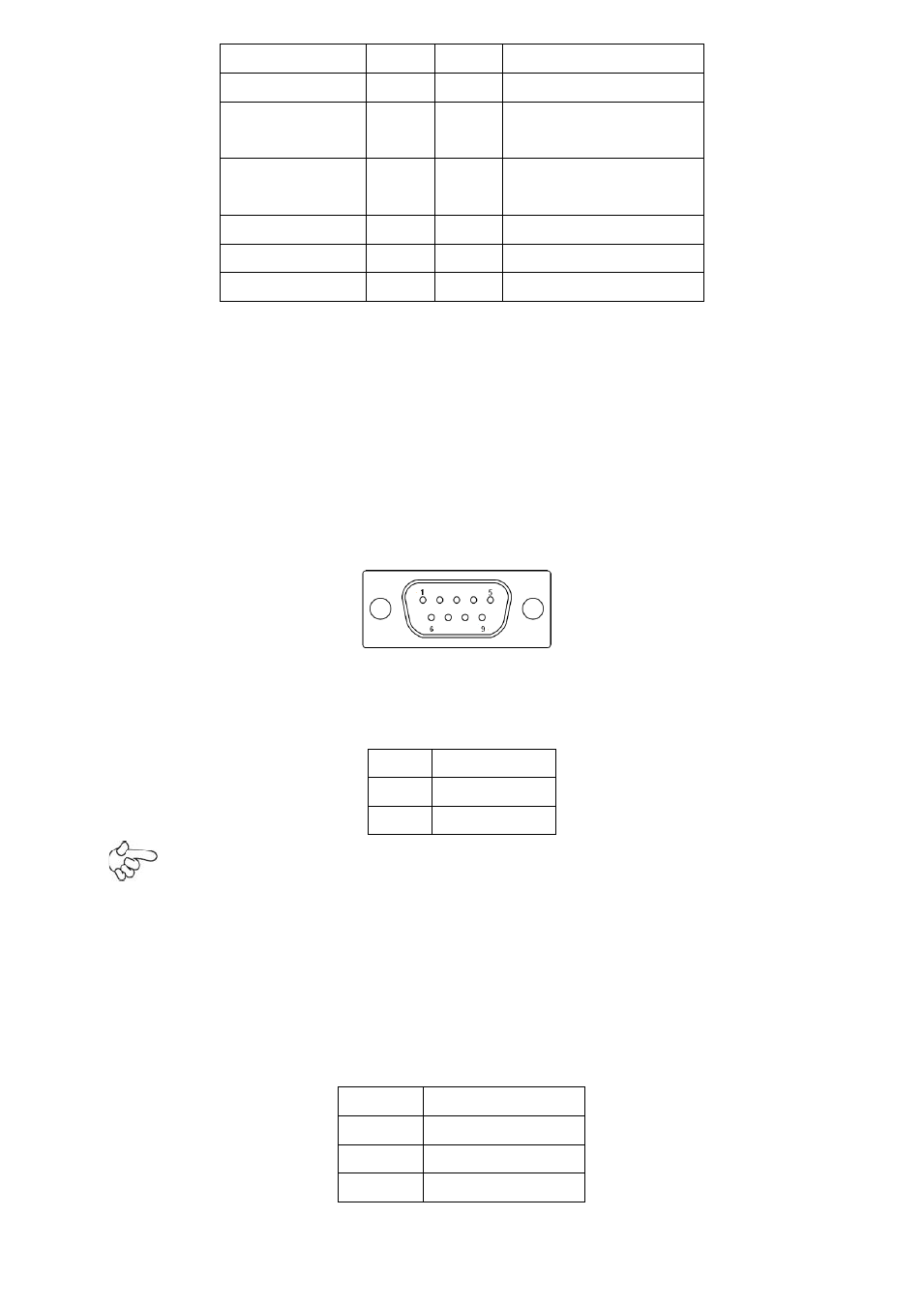
20. COM1: (Type DB9),
Rear serial port, standard DB9 serial port is provided to make
a direct connection to serial devices. COM1 port is controlled by pins No.1~6 of
JCOM,select output Signal RI or 5V or 12v, For details, please refer to description of
JCOM.
21. AT12V:
(5.0mm 1x2 Pin Connector),DC12V System power input connector。
Pin#
Signal Name
1
+12V
2
Ground
Note:
Make sure that the voltage of power supply is DC(12±5%)V before power on, or
it may cause boot up failure and even system damage.
22. FAN:
(2.54mm Pitch 1x3 Pin Header),Fan connector, cooling fans can be
connected directly for use. You may set the rotation condition of cooling fan in menu of
BIOS CMOS Setup.
Pin#
Signal Name
1
Ground
2
VCC
3
Rotation