Aplex Technology ACS-2120 User Manual
Page 22
ACS-2120 User Manual
22
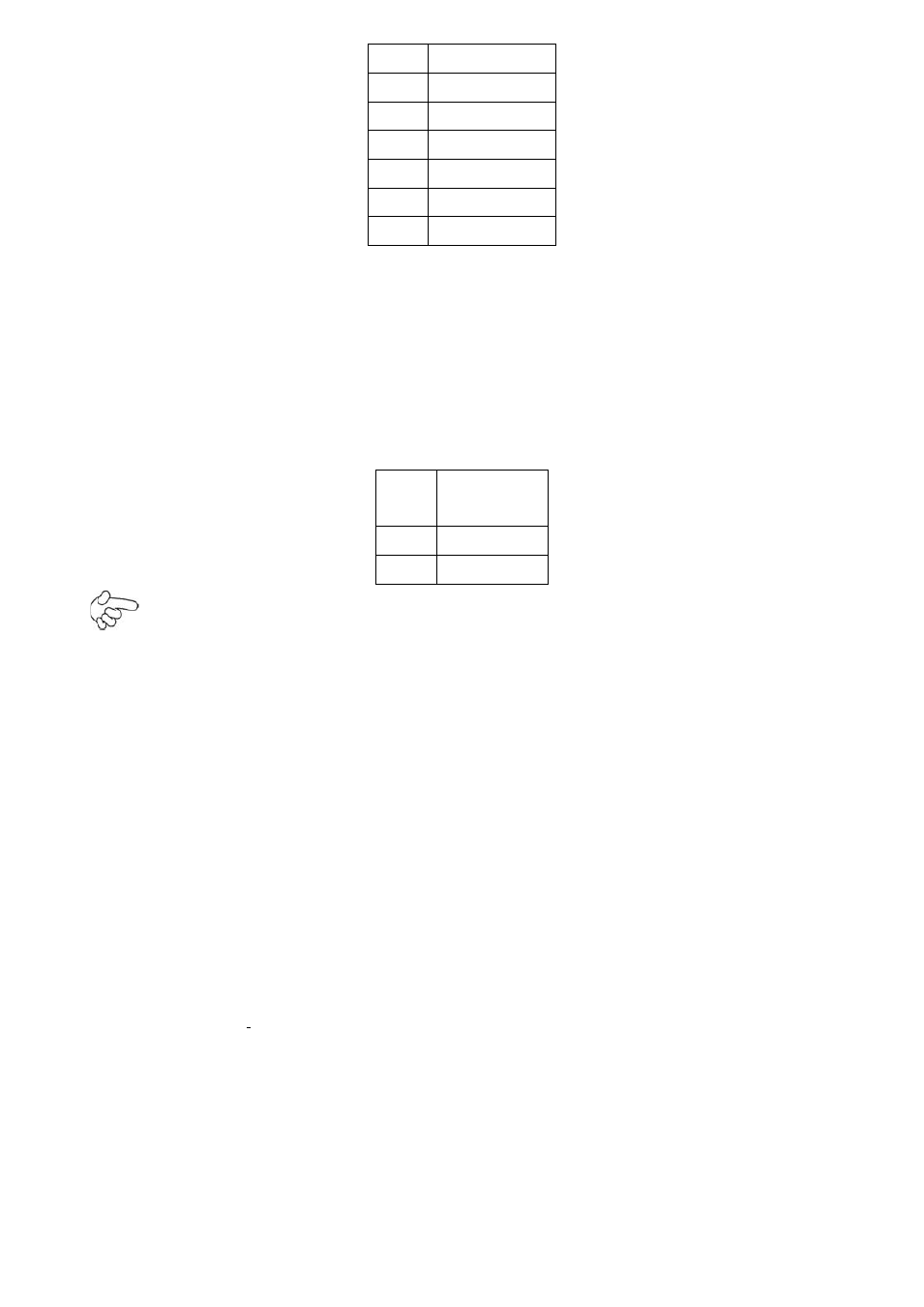
Pin#
Signal Name
1
+DC12V
2
+DC12V
3
Ground
4
Ground
5
BKLT_EN
6
BKLT_CTRL
26. SATA1/2/3:
(SATA 7P),SATA1,SATA2,SATA3
SATA Connectors,Three SATA connectors
are provided, with transfer speed up to 3.0Gb/s.
27. CN1:
(2.5mm Pitch 1x2 box Pin Header),an onboard 5V output connector is
reserved to provide power for IDE/SATA devices.
Pin#
Signal
Name
1
+DC5V
2
Ground
Note:
Output current of the connector must not be above 1A.
28. PC104+:
(4x30 Pin),
PC104 plus connector, it conforms to standard PC104+ specifi-
cation.
29. MPCIE2:
(30mmx30mm Socket 52Pin),mini PCIE socket, it is located at the top, it
supports mini PCI-E devices with USB2.0, SMBUS and PCI-E signal.
30. MPCIE2 SCREW HOLES:
one screw holes for fixed MPCIE2 assemble.
31. MPCIE:
(50.95x30mm socket 52Pin),mini PCIE socket, it is located at the bottom,
it
supports mini PCI-E devices with USB2.0, SMBUS and PCI-E signal.
32. CF:
CF
Card socket, it is located at the bottom of the board and serves as an insert
interface for Type I and Type II Compact Flash card. The operating voltage of CF card
can be set as 3.3V or 5V. The default setting of the product is 3.3V.
33. DDR3:
(SO-DIMM 204Pin socket), DDRIII memory socket,
the socket is located at the
bottom of the board and supports 204Pin 1.5V DDRIII 800MHz FSB SO-DIMM
memory module up to 2G.