Beisler 1500-70-2 User Manual
Page 38
2-14
M8
M7
M6
M5
M4
M3
M2
M1
F12
F11
F10
F9
F8
F7
F6
F5
F4
F3
F2
F1
SETUP
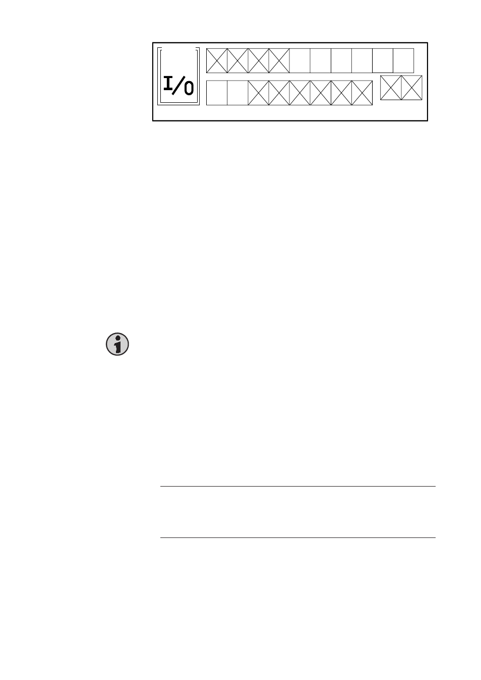
-10
All inputs (F1 ... F12) and outputs (M1 ... M8) are displayed on this page. For
diabled inputs/outputs, the respective icon is crossed out.
At this machine, outputs F1 ... F4, F11 and F12, and inputs M3 ... M8 must
be disabled. Position the cursor on the icon of an input/output and press the
Plus/Minus key to alter the setting.
The outputs are valves and occupied as follows:
Valve description
Output connector
F1 Y1
Lift sewing foot
pin 1
F2 Y2
Thread cutter
pin 3
F3 Y3
Needle cooling
pin 5
F4
Thread wiper
is not layed upon
F5 Y5
Pinking up/down (pressure 3 bar)
pin 9
F6 Y6
Tape cutter
pin 11
F7 Y7
Blow out needle threads
pin 13
F8 Y8
Waste suction
pin 15
F9 Y9
Blow out parts
pin 17
F10 Y10 Pinking up/down (pressure 5 bar)
pin 19
The inputs are occupied as follows:
Description
Input connector
M1
Safety switch for thread cutter monitoring pin 2-4
M2
Switch for tape cutter
pin 4-6
3.7
Program inputs and outputs
The inputs and outputs can be enabled/disabled on setup page -10. Enabled
inputs and outputs can be programmed.
To program an input or output, position the cursor on the respective icon and
press the Special key. The setup page will be opened.
Hint
The programming of inputs and outputs is not executed program-specific.
The setting is the same for all programs. Modifications effect all sewing
programs.
3.7.1
Setup page of inputs and outputs