Dc power connections, 2 dc power connections – BSS Audio MSR-602/604II Owner's Manual User Manual
Page 13
11
ent connection of line to line rather than line to neutral phase voltages
when using a three phase supply. In either case internal transient
suppressors (VDRs) can become damaged and will consistently blow
replacement fuses. You may be assured that they have protected your
unit from damage, but they will need removal to allow further use of
your unit, and should be replaced as soon as possible to ensure con-
tinued protection. If you feel this has happened, please refer to the
appropriate section at the rear of this manual for the removal and
replacement procedure.
DC connection between the MSR-604 II units and the MSR-602 II power
supply is by the integral multicore cable with 9 pin D connectors. Note
that the MSR-602 II power supply must always be located above the
MSR-604 II units. (NB - this is opposite to the way early MSR-604s were
racked.) Having the power supply at the top gives superior hum
performance, and also places the HEADROOM meter and headphone
amplifier in the most convenient position where they will not be
obscured by cable looms from the FEED outputs. (Fig 4)
The topmost MSR-604 II’s LOOP IN cable is plugged into the power
supplies LOOP OUT connector. Each remaining MSR-604 II is
connected to the unit above it in similar fashion. Finally the male to
female multicore D cable packed with the MSR-602 II is used to loop the
final MSR-604 II’s LOOP OUT connector back to the LOOP RETURN
socket on the power supply.
This ‘ring’ circuit allows a more reliable system set up, since an indi-
vidual MSR-604 II may be isolated and removed from the rack without
disturbing the power to the rest of the system. Ensure that the JACK
SCREWS on the connectors are secured and tightened.
DC Power Connections
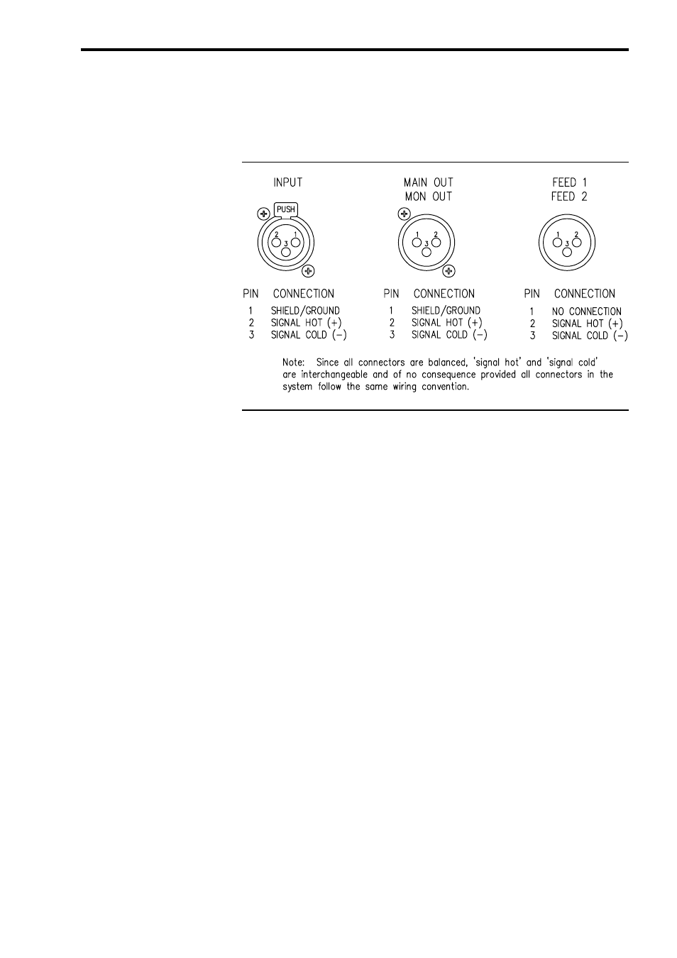
Fig. 5 Cable Wiring
Details
3.2 DC Power
Connections