Msr-600 ii series – BSS Audio MSR-602/604II Owner's Manual User Manual
Page 26
Advertising
2 4
MSR-600 II Series
Multiple Output Distribution Amplifier Configuration
Stereo Summing Configuration
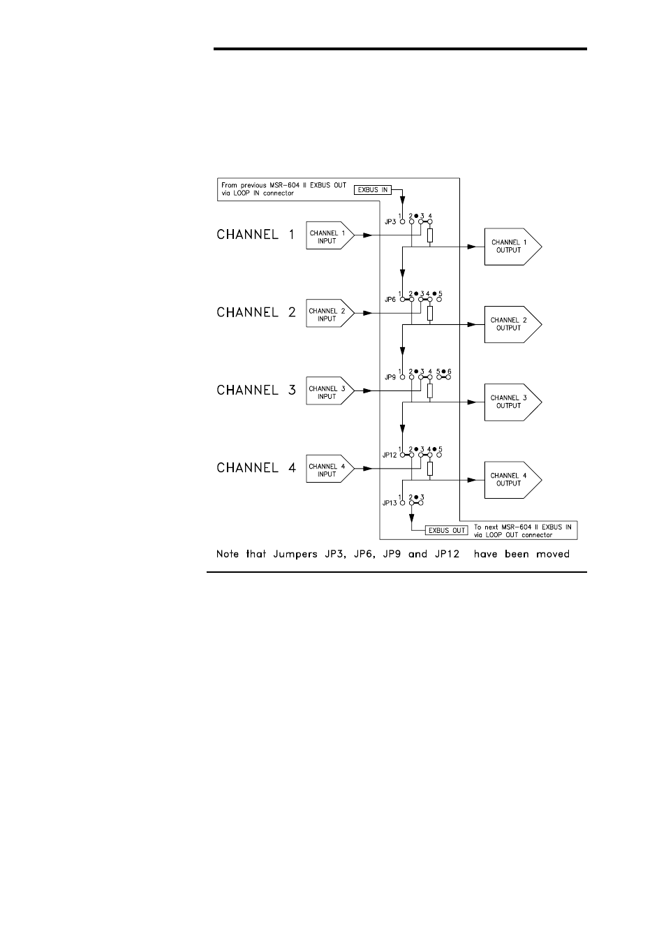
Fig. 13B Bus Linking
In1+In2 Drives Out1 and 2
In3+In4 Drives Out3 and 4
When a group of channels is linked as a D.A., the controls associated
with the chosen input section are used to set the required operating
conditions. the controls on the other channels are disabled, except for
the CLIP LEDs and the LISTEN switches which may be used to confirm
that the signal is reaching all the linked output stages.
Figure 13B above shows an alternate bus configuration where a
stereo pair of inputs is used to drive two output channels in parallel.
Each output is a sum of the pair of inputs reduced by 6dB.
CONTROLS
4.7 Stereo Summing
Configuration
Advertising