Msr-600 ii series – BSS Audio MSR-602/604II Owner's Manual User Manual
Page 30
2 8
MSR-600 II Series
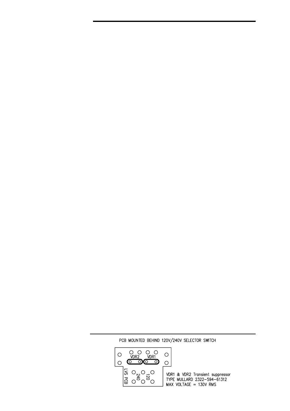
Transient Suppressor Replacement
Fig. 15 Transient
Suppressor Details
balanced 10dB pad using a relay controlled by a circuit which moni-
tors the MAIN OUTPUT XLR for the presence of phantom DC voltage.
The balanced signal then passes through the optional input trans-
former, if fitted, and DC blocking capacitors to the low noise INPUT
AMPLIFIER. This stage provides the common mode rejection trim,
GAIN switch and provides a line level low impedance unbalanced
drive signal to the BUS LINKING HEADERS. In the default mode the
channel signal is not routed to the bus but is passed to the channel
output stages.
The OUTPUT AMPLIFIER has two out of phase line driving outputs
which are DC blocked and passed to both the balanced MAIN OUTPUT
ATTENUATOR and the balanced MONITOR OUTPUT ATTENUATOR.
The signals are then fed to the MAIN OUT and the MON OUT XLRs
respectively. The low impedance attenuators ensure that a faulty cable
or load on one output will not affect the other and also allow the output
drive levels to be independently set to +23dBu, +13dBm, or +3dBm at
clip. If the optional output transformers are installed, they are fitted in
place of the attenuators and the output headroom is preset at +3dBu.
The FEED AMPLIFIER buffers the signal and drives the dual secondary
isolating FEED TRANSFORMER which is connected to the two FEED
output XLRs mounted on the front panel.
The LISTEN AMPLIFIER buffers the signal before presenting it to the
LISTEN switch. This in turn is connected to the listen bus for monitor-
ing on the HEADROOM METER and HEADPHONE AMPLIFIER which
are located in the MSR-602 II power supply.
The primary of the mains transformer within the MSR-602 II is pro-
tected against high voltage spike interference by two voltage depend-
ent resistors. These provide a short circuit to voltage peaks in excess
of their maximum rating.
Should the MSR-602 II be inadvertently connected to 3 phase line/line
voltages, or to 240V when selected to 120V, or any other incorrect
voltage, these suppressors are likely to fail in a protective short circuit
mode. This will be demonstrated by repeated mains fuse failure when
powering up the unit.
Even in this case of extreme overvoltage, the MSR-602 II is protected
against failure, and the simple removal of these suppressors will allow
the unit to be used again. However, it is important that they are
replaced as soon as possible to ensure continued protection.
6.2 Transient
Suppressor
Replacement