BSS Audio MSR-602/604II Owner's Manual User Manual
Page 25
23
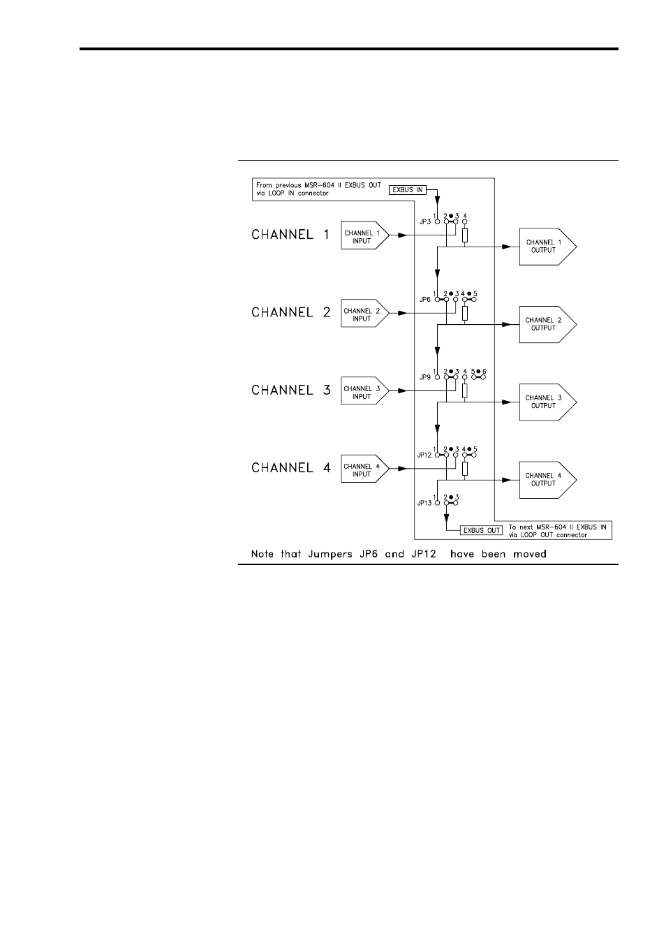
Fig. 13A Bus Linking
Ch1 Drives Out1 and 2
Ch3 Drives Out3 and 4
Multiple Output Distribution Amplifier Configuration
The signal labelled EXBUS-OUT passes via the LOOP OUT connector
to the EXBUS-IN terminal in the LOOP IN connector on the adjacent
unit, allowing a D.A. channel to span more than one MSR-604 II unit.
It will be apparent from the above example that the permutations of
D.A. blocks that can be configured within a system is limited only by
the number of MSR-604 IIs that are connected in the rack.
The limiting factor on how many channels may be linked is the paral-
lel loading that occurs on the drive from the input stage. The recom-
mended maximum is sixteen, which equates to sixty four outputs. This
will result in an overall drop in system gain of about 0.7dB but should
not significantly affect noise or distortion.
It is strongly advised that in order to have a configuration work first
time, that the required system is first planned out on paper, and with
reference to Figures 12, 13A and 13B, a list of jumper settings is
produced. Implementing the system then becomes a simple mechani-
cal task of setting the relevant jumpers.