Msr-600 ii series – BSS Audio MSR-602/604II Owner's Manual User Manual
Page 24
2 2
MSR-600 II Series
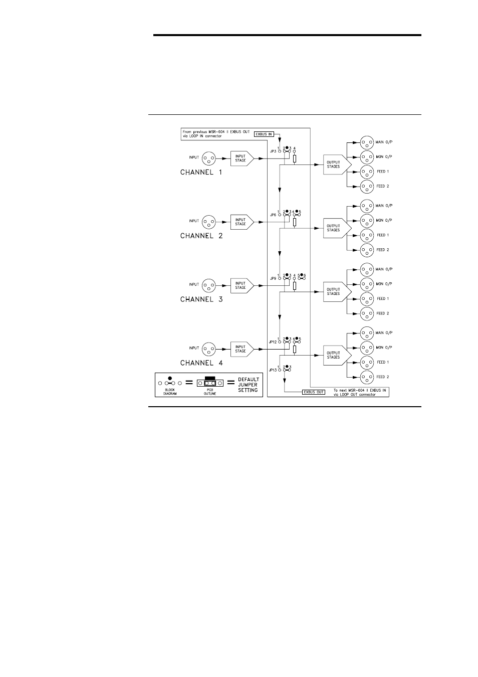
Fig. 12 Bus Linking Block
Diagram.
Default Jumpers
Multiple Output Distribution Amplifier Configuration
JUMPER SETTING
For use as a distribution amplifier, or in any situation where more than
four outputs per channel are required, the MSR-604 II system may be
reconfigured by moving internal jumpers. Up to sixteen adjacent
channel sections, a total of sixty four outputs may be driven from a single
input stage.
The simplified block diagram, Figure 12 shows the segmented internal
bus which runs between adjacent channels. This bus is continued via
the multiway LOOP connector between MSR-604 II units, allowing
blocks of D.A. channel to span several output sections. Figure 12
shows the bus and the bus linking headers in their default settings, i.e.
each channel input section is connected to its own output section.
The default jumper positions are identified on the PCB by a white
block printed adjacent to the relevant jumper pins. By way of exam-
ple, Figure 13A illustrates a typical distribution amplifier arrangement
where Channel 1 input section is used to drive its own and Channel
2’s output sections and, likewise, Channel 3 input is driving the out-
puts of both Channel 3 and Channel 4.
4.6 Multiple
Output Distribution
Amplifier
Configuration