0 introduction, Msr-600 ii series – BSS Audio MSR-602/604II Owner's Manual User Manual
Page 6
4
MSR-600 II Series
1.0
Introduction
Introduction
It is not uncommon within a sound system which uses microphones as
a source of programme, for that microphone to be connected to the
input of a number of different processing facilities.
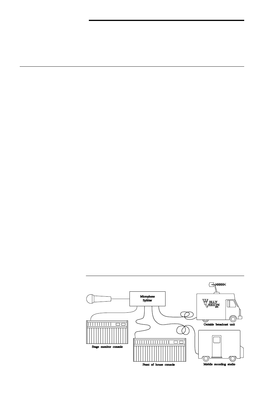
An example of this would be in sound reinforcement work where a
stage microphone is required to drive the main ‘front of house’ mixing
console, the stage monitoring mixing console, a mobile recording studio
and quite possibly an outside broadcast recording vehicle.
It is also common within such a system for the microphone to be
connected to considerable lengths of shielded cable before being
terminated at the processing facilitys input connector.
Such a load on the microphone is very much in excess of its design
capability, and as a consequence the level and quality of the sound is
impaired. (Fig. 1)
A further complication can arise within such a system from multiple
earthing as each of the processing facilities would be providing its own
ground.
To overcome these problems it is quite common for a multiple winding
transformer to be used which provides separate secondary windings for
each of the required outputs. This solution will solve the multiple
grounding problems, however it does not tackle the sound level and
quality problem as, being a passive device, it has no power amplification
capability.
Cost effective active electronic solutions proved elusive until the
introduction of the original BSS MSR-604 overcame the problems of
noise and headroom. The current MSR-604 II further improves upon the
performance of the original unit with yet greater dynamic range,
Fig. 1 Microphone
Loading