0 appendix a – BSS Audio MSR-602/604II Owner's Manual User Manual
Page 29
Advertising
27
advice if a replacement or a second power supply is required for a Mk
I system.
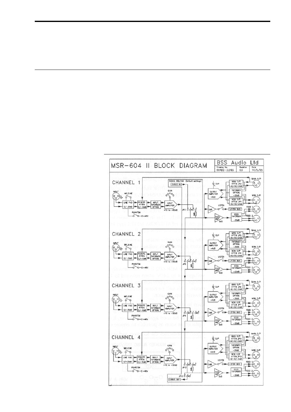
Figure 14 shows the block diagram of the audio section of the MSR-
604 II. The DC supply regulator circuits (not shown) are common to
all channels. The rails to each channel are protected by fusible
resistors so that in the event of a short circuit fault in one channel the
other three are not affected.
The input signal passes via RFI filters to the MIC/LINE switch, a bal-
anced 20dB pad, and then to the REMOTE ATTENUATOR. This is a
6.0
Appendix A
6.1 System Block
Diagram and
Circuit Description
Appendix A
System Block Diagram and Circuit Description
Fig. 14 MSR-604 II Block
Diagram
Advertising