6 microphone inputs – Cloud Electronics CX462 User Manual
Page 11
CX462 Audio System Controller
Setup And Installation Guide
CLOUD ELECTRONICS LIMITED
5
V3 280904
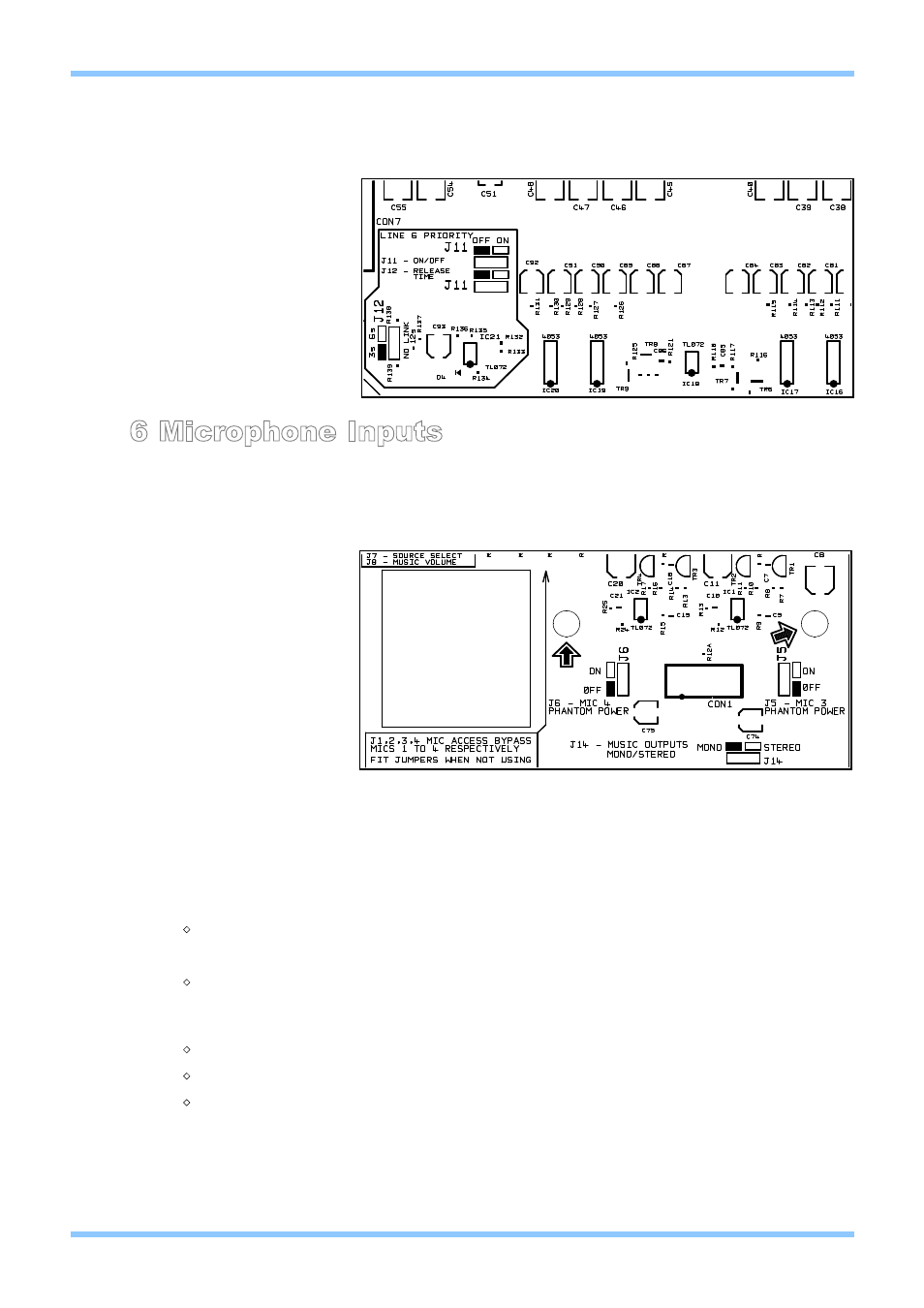
Line 6 Priority continued
6 Microphone Inputs
Four microphone inputs are provided each having electronically balanced, transformer-less circuitry
configured for optimum low noise performance. The input impedance is greater than 2kΩ and suitable for
microphones in the 200Ω to 600Ω range. Inputs are via 3-pin plug in screw terminal type connectors
(Phoenix type) located on the rear panel. A facility to provide 15V phantom power is included for each
microphone that is activated by setting the relevant internal jumpers from the list below to the ‘ON’
position:
NOTE: Microphones one and two have their jumpers located on the upper microphone input circuit
board.
When setting the jumper(s) please ensure that you:
M Remove the mains cable from the rear of the product before removing the top panel.
M Only reassemble the unit using screws identical to the original parts.
All microphone inputs are balanced with the following pin configuration:
M Pin 1 - GROUND
M Pin 2 - COLD/INVERTING
M Pin 3 - HOT/NON-INVERTING
To connect an unbalanced microphone to the input, use pins 1 and 3 with pin 2 connected to ground
(Pin 1).
J18:
Mic 1 phantom power
J19:
Mic 2 phantom power
J5:
Mic 3 phantom power
J6:
Mic 4 phantom power
Location of Jumpers J5 & J6
Location of Jumpers J11 & J12
Line 6 Priority
Jumpers
J11: Priority on/off
J12: Release time
3s
6s
12s