Comtech EF Data RCS11 User Manual
Page 30
RCS11 1:1 Redundancy Switch
User Interfaces
MN-RCS11 – Revision 9
3–2
from Modem A or B
SELECT Demod A or
B (Pushbutton)
--------------------
Allows the operator to
select a Demodulator: A
or B
Modulator Controls and Indicators
Online LED
Indicates which
Modulator is online:
A or B
LED illuminates green
for Online
Fault LED
The RCS11 has
received a fault from
Modulator A or B
LED illuminates Red for
Fault
SELECT Mod A or B
(Pushbutton)
----------------------
Allows the operator to
select a Modulator: A or
B
3.3
Rear Panel Interface
3.3.1 System Installation and Connections
3.3.1.1
RCS11 with Universal G.703 Interface
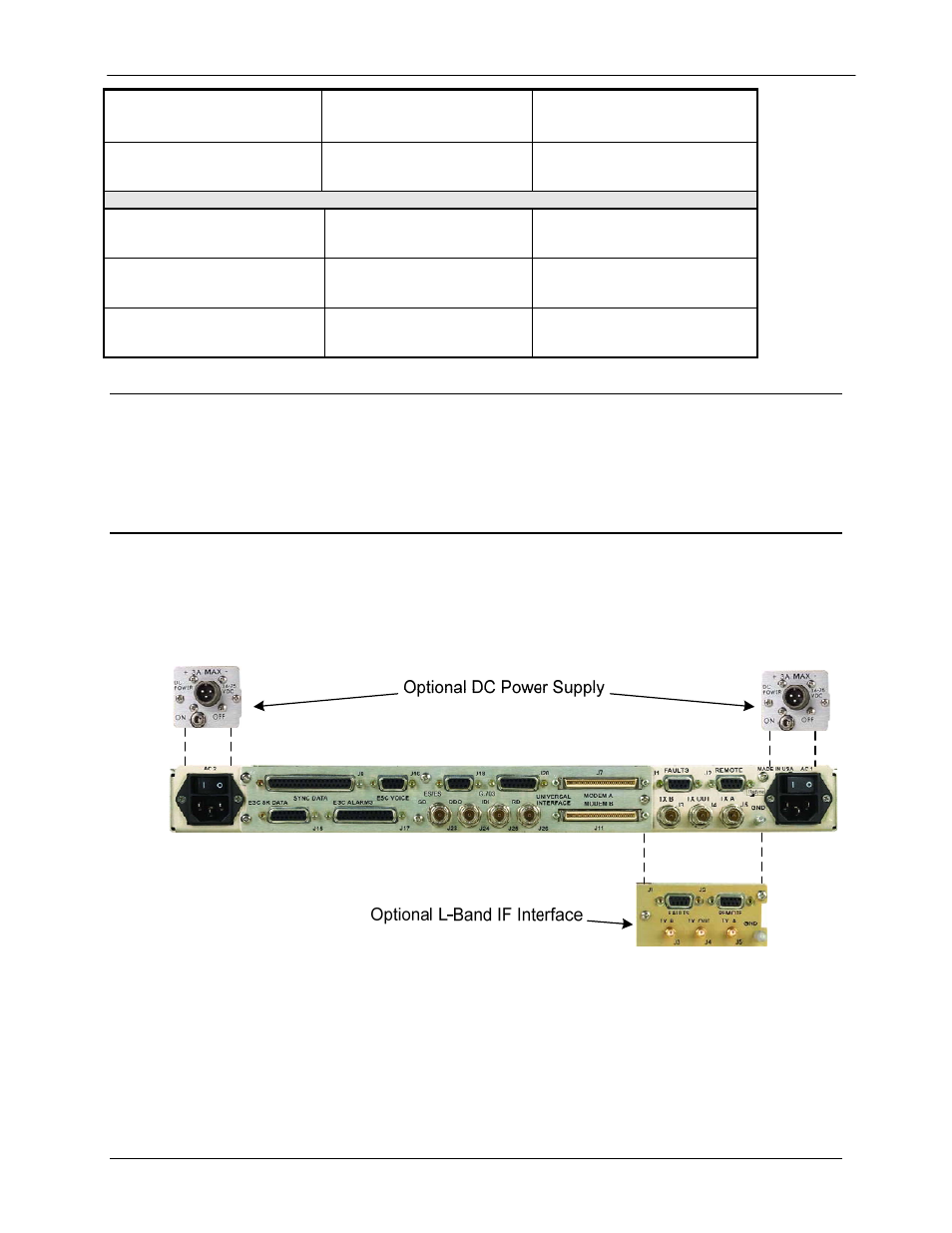
Figure 3-1 illustrates the RCS11 with the Universal G.703 Interface available with either AC or DC
power entry and 70/140 or L-Band Intermediate Frequency. Table 3-1 describes the connection
hardware required.
Figure 3-1. RCS11 with the Universal G.703 Interface