Comtech EF Data RCS11 User Manual
Page 56
Advertising
RCS11 1:1 Redundancy Switch
Installation
MN-RCS11 – Revision 9
4–18
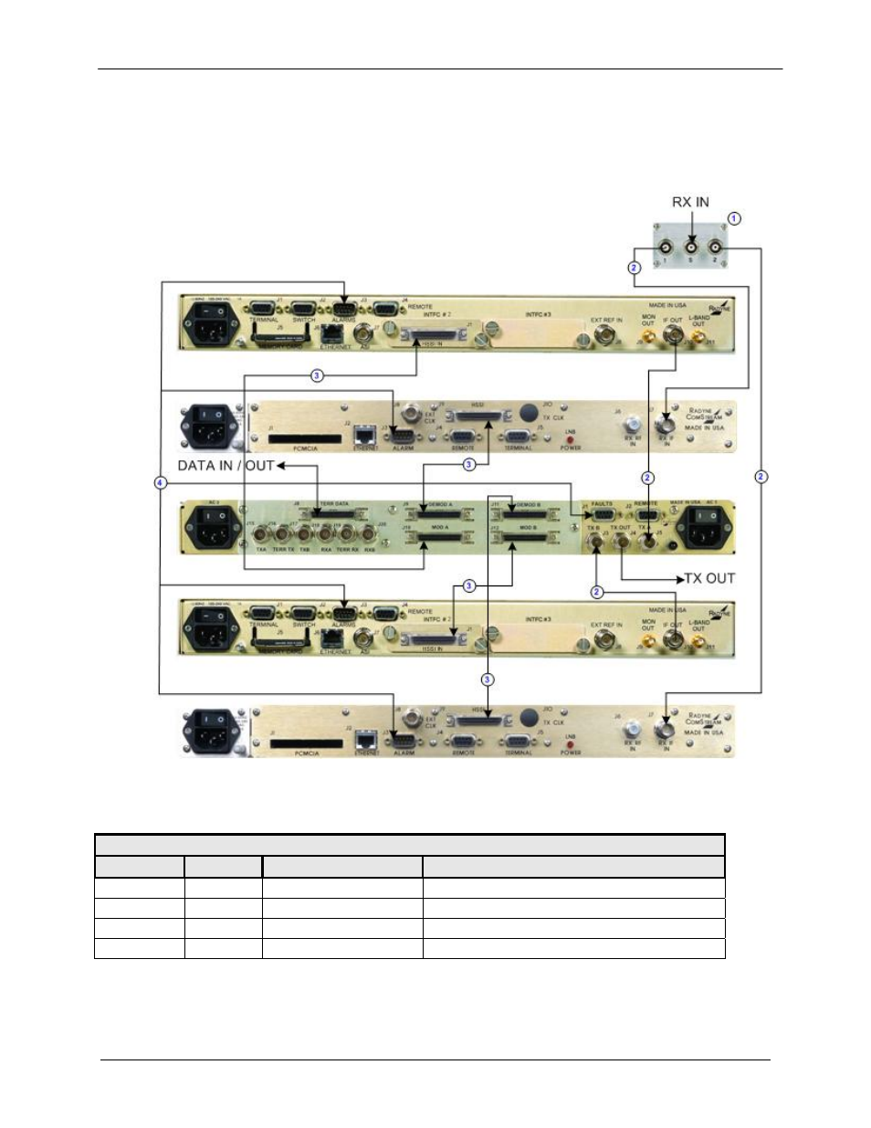
4.6.15
DM240XR & DD240XR
Figure 4-15 illustrates an RCS11 1:1 system with the HSSI / ASI Interface connected to
DM240XR Modulators and DD240XR Demodulators utilizing the HSSI Interfaces. Table 4-15
describes the connection hardware required.
Figure 4-15. RCS11 with HSSI / ASI Interface Connected to DM240XR Modulators and
DD240XR Demodulators with HSSI Interfaces
Table 4-15. Connection Hardware
Item No.
Quantity
Part Number
Discription
1
1
RF/ZSC-2-175
70/140 IF Splitter
2
4
CA/3598-36
3’ BNC to BNC 75 Ohm Coaxial Cable
3
4
CA/3841-2
2' HSSI Data Cable
4
1
CA/3865
Alarm Fault Cable
Advertising