Comtech EF Data RCS11 User Manual
Page 43
RCS11 1:1 Redundancy Switch
Installation
MN-RCS11 – Revision 9
4–5
Table 4-1. Connection Hardware
Item No.
Quantity
Part Number
Discription
1
1
RF/ZSC-2-175
70/140 IF Splitter
2
4
CA/3598-36
3’ BNC to BNC 75 Ohm Coaxial Cable
3
2
CA/3407-3
3’ SCSI Data Cable
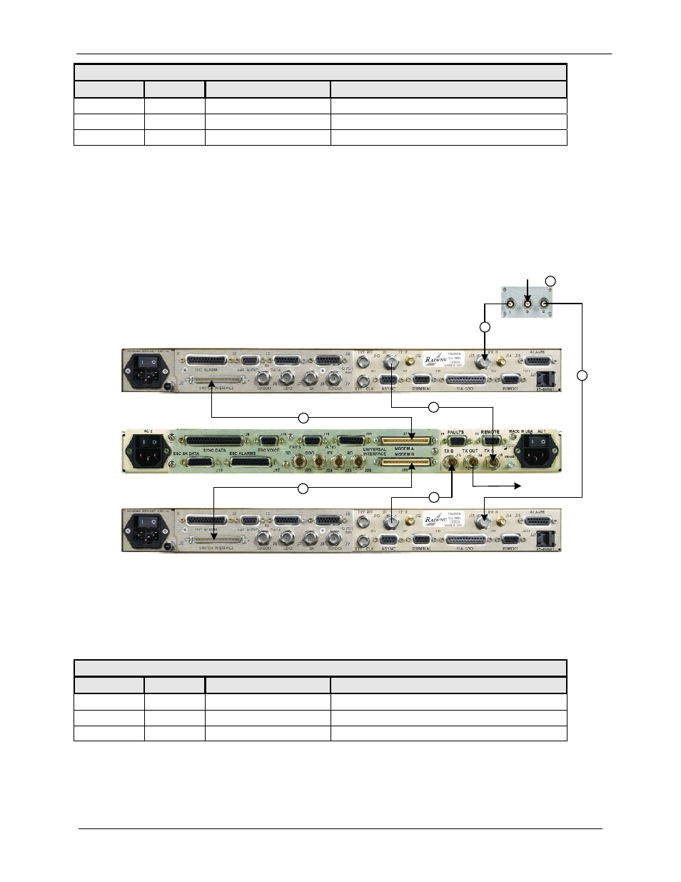
4.6.2 DMD20, DMD50 or DMD2050 Universal with G.703 IBS/IDR Interface
Figure 4-2 illustrates a 1:1 system using the RCS11 with the Universal Interface connected to
DMD20 Modems with 70/140 MHz IF configuration and G.703 IBS/IDR Interfaces. Table 4-2
describes the connection hardware required.
RX IN
TX OUT
1
2
2
3
3
2
2
Figure 4-2. RCS11 with Universal Interface Connected to DMD20, DMD50 or DMD2050
Modems with G.703 IBS/IDR Interfaces
Table 4-2. Connection Hardware for 70/140 MHz Option
Item No.
Quantity
Part Number
Discription
1
1
RF/ZSC-2-175
70/140 IF Splitter
2
4
CA/3598-36
3’ BNC to BNC 75 Ohm Coaxial Cable
3
2
CA/3407-3
3’ SCSI Data Cable