Comtech EF Data RCS11 User Manual
Page 81
RCS11 1:1 Redundancy Switch
Connector Pinouts
MN-RCS11 – Revision 9
5–23
5.10.2 Ethernet
Interface
The Ethernet interface can support 10/100/1000 Base-T.
5.10.2.1 DATA
B
(J27)
Modem B Data Port is an RJ45 Connector.
5.10.2.2 TERR
DATA
(J28)
The TERR TX User Data Port is an RJ45 Connector.
5.10.2.3 DATA
A
(J29)
Modem A Data Port is an RJ45 Connector.
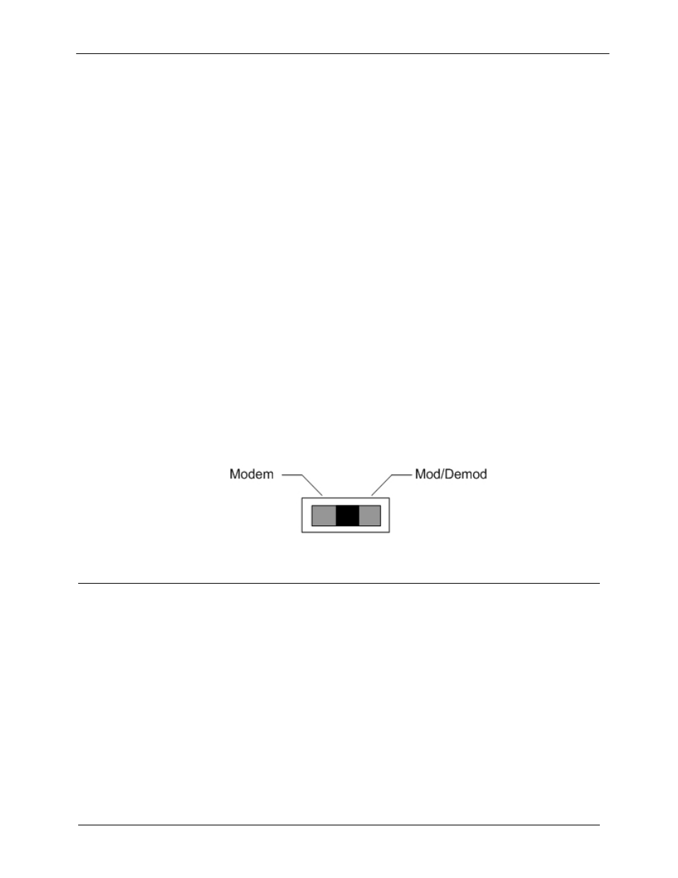
5.10.2.4 SWITCH
(S1)
The RCS11 Ethernet interface can be configured to support a modem or Modulator/Demodulator.
The S1 switch must be properly set to the correct position to support the modem or
Modulator/Demodulator.
NOTE: On the S1 Switch moving the switch to the left sets the unit to the Modem Feature,
moving the switch to the right sets the unit to the Mod/Demod Feature.
NOTE: Power must be cycled after changing S1 to desired setting for effect to take place.
Figure 5-2. RCS11 S1 Switch Diagram
5.11 SERIAL
INTERFACE
The RCS11, RS449 Serial Interface supports RS422 Serial Data. This interface is supported by
the the DMD20 and DMD50.