3 rcs11 parallel interface – Comtech EF Data RCS11 User Manual
Page 33
Advertising
RCS11 1:1 Redundancy Switch
User Interfaces
MN-RCS11 – Revision 9
3–5
3.3.1.3
RCS11 Parallel Interface
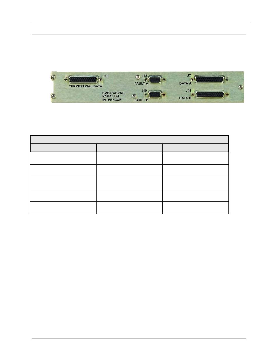
Figure 3-3 illustrates the RCS11 DVB Parallel Data Interface (RS422 and LVDS Parallel). Table
3-3 describes the connection hardware required.
Figure 3-3: RCS11 DVB Parallel Interface (RS422 and LVDS)
Table 3-3. Connection Hardware
LOCATION
CONNECTOR
DESCRIPTION
J7 DATA A
25-Pin F D Sub
Parallel RS422 and
LVDS Data A
J10 TERRESTRIAL
DATA
25-Pin F D Sub
Parallel Data Input
J11 DATA B
25-Pin F D Sub
Parallel RS422 and
LVDS Data B
J18 FAULT A
9-Pin F D Sub
Alarm Fault Primary
Device
J19 FAULT B
9-Pin F D Sub
Alarm Fault Back Up
Device
Advertising