2 remote (j2) – Comtech EF Data RCS11 User Manual
Page 60
RCS11 1:1 Redundancy Switch
Connector Pinouts
MN-RCS11 – Revision 9
5–2
5.4
RCS11 COMMON CONNECTIONS
5.4.1 FAULTS (J1)
The Fault Port is a 9-Pin Female ‘D’ Connector. This does not include the HSSI interface. Refer
to Table 5-2 for pinouts.
Table 5-2 Fault Port – 9-Pin Female ‘D’ Connector
Pin No.
Description
Status
1
Switch Fault Relay
Common
2
Switch Fault Relay
Normally Open
3
Mod B Selected Relay
Normally Closed
4
Demod B Selected Relay
Common
5
Demod B Selected Relay
Normally Open
6
Switch Fault Relay
Normally Closed
7
Mod B Selected Relay
Common
8
Mod B Selected Relay
Normally Open
9
Demod B Selected Relay
Normally Closed
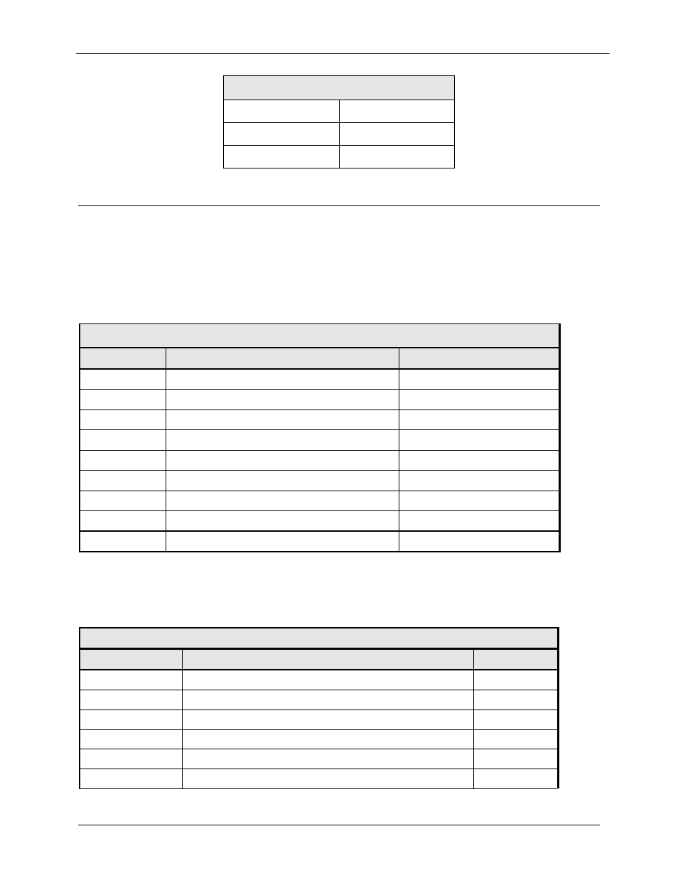
5.4.2 REMOTE (J2)
The Remote Control Port is a 9-Pin Female ‘D’ Connector. Refer to Table 5-3 for pinouts.
Table 5-3. Remote Port – 9-Pin Female ‘D’ Connector (J2)
Pin Number
Description
Signal
1
*RS-485 Remote RLLP Select
2 RX
RS232
Input
3 TX
RS232
Output
4 NC
NA
5 Ground
GND
6
RX (A) – RS485
Input
Table 5-1 DC Power
A
-
B Ground
C
+