External connection, Chapter 3. external connections, 1 external connections – Comtech EF Data SDM-2020 User Manual
Page 41
3–1
Chapter 3. EXTERNAL
CONNECTIONS
This chapter a description of external connections.
3.1 External
Connections
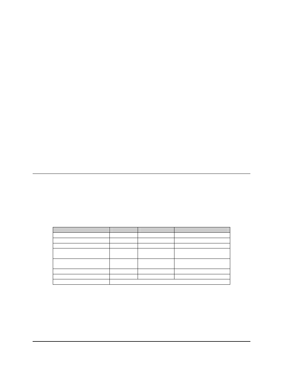
The connectors for the main unit are shown in figure 3-1 or Figure 3-2 and Rear Panel RF
Input Connectors (Table 3-1).
Table 3-1. Rear Panel Connectors
Name
Ref. Desig.
Type
Function
Remote
J1
9-pin D, Female
Remote control (M&C)
Fault
J2
9-pin D, Female
Relay Faults
Monitor
J21
9 pin D, Female
Performance Monitor
IF Input (Single-Channel)
(see Note 1)
J23
Type F, Female
RX IF input, LNB power out.
IF Input (4 Input)
(see Note 2)
J23, J24,
J25, J26
Type F, Female
RX IF Input LNB power out
Prime Power
None
Standard
AC Power Input
GND
None
#10-32 Stud
Chassis Ground
Data Interface Connectors
See Applicable Chapter
Notes:
1. Single RX IF input is for earlier L-Band units and all 70/140 MHz demodulators. LNB
power is available only for L-Band.
2. The 4-channel input IF is only available for L-Band.