1 connector pinout definitions – Comtech EF Data SDM-2020 User Manual
Page 43
SDM-2020 Satellite Demodulator
Revision 4
Installation
MN/SDM2020D.IOM
3–3
3.1.1
Connector Pinout Definitions
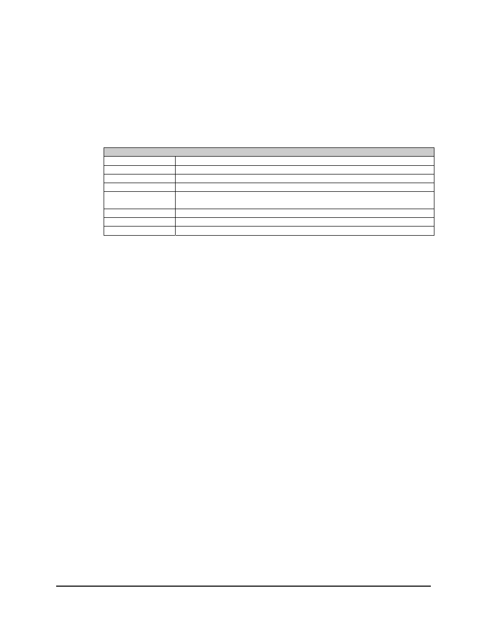
Pinout “TYPE” is defined to described signal direction for each pin. The signal direction
is relative to the connector.
Definitions for Pinout Types
I (Input)
A signal goes into the connector.
O (Output)
A signal exits the connector.
I/O (Input/Output)
A signal both enters and exits the connector on the specified pin.
GND (Ground)
The pin is defined as being connected to a power supply ground or return.
N/A (Not Assigned)
The pin is not assigned within the system but may be routed to other connectors.
Usually defines spare pins.
N/C (No Connect)
The pin is not connected and is not used within the system.
N/U (Not Used)
The pin is not used but is routed and has other uses within the system.
FC (Form C)
The pin is connected to a “Form C” relay.