4 viterbi decoder, 4 viterbi decoder 5.4.1 description, 2 specifications – Comtech EF Data SDM-9000 User Manual
Page 144
Theory of Operation
SDM-9000 Satellite Modem
5–16
Rev. 4
5.4 Viterbi Decoder
5.4.1 Description
The modem Viterbi decoder circuitry is located on the demodulator PCB (bottom slot of
the modem chassis) and operates in conjunction with the convolutional encoder at the
transmit modem. The decoder uses a decoding algorithm to provide FEC on the received
data stream for errors occurring in the transmission channel.
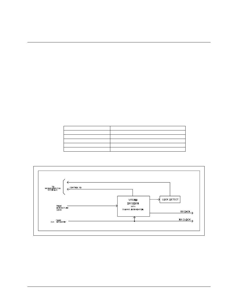
A block diagram of the Viterbi decoder is shown in Figure 5-5.
5.4.2 Specifications
BER
See Figure 1-4 and Table 1-2
Maximum Data Rate
25 Mbit/s (on each of 3 channels)
Synchronization Time
8000 bits (maximum)
Output Fault Indicators
Activity detection of I and Q data sign bits
Raw BER Detection
From 0 to 255 bits out of 1024 samples
Constraint Length
7
Figure 5-5. Viterbi Decoder Block Diagram